|
||||||||||||||||||||||
 |
||||||||||||||||||||||
 |
 |
 |
 |
 |
 |
 |
 |
|||||||||||||||
 |
 |
 |

|
 |
 |
 |
 |
|||||||||||||||
 [Click for more ...]") |
||||||||||||||||||||||
| Last Updated: Mon Jan 27 11:18:09 UTC 2014 | ||||||||||||||||||||||
|
||||||||||||||||||||||
|
||||||||||||||||||||||
|
||||||||||||||||||||||
|
|
|
|
|
|
|
|
|||||||||||||||
|
|
|
|
|
|
|
|
|||||||||||||||
|
||||||||||||||||||||||
| Last Updated: Mon Jan 27 11:18:09 UTC 2014 | ||||||||||||||||||||||
|
||||||||||||||||||||||
| Warsaw
Pact
/
Russian
/
PLA Emitter Locating Systems / ELINT Systems Technical Report APA-TR-2008-0503 |
||||||||||||||||||||||||||||||||||||||||||||||||||||||||
|
||||||||||||||||||||||||||||||||||||||||||||||||||||||||
(Images Czech MoD, RuMoD,
Topaz, ERA, Miroslav
Gyűrösi, Vitaliy Kuzmin, Other)
 The Ukrainian Topaz Kolchuga ESM
system
has received considerable press over the last decade, mostly related to
alleged illegal sales to Saddam's regime preceding Operation Iraqi
Freedom (Image © Miroslav Gyűrösi).
|
||||||||||||||||||||||||||||||||||||||||||||||||||||||||
IntroductionA topic which appears to crop
up with monotonous regularity in the overseas press is that of alleged
sales or smuggling to nations hostile to the US of former Warsaw Pact
equipment "capable of detecting stealth aircraft". These claims
invariably involve either the Czech designed and built Tesla-Pardubice
KRTP-86 Tamara or ERA Vera Emitter Locating Systems, or the Ukrainian
designed and built Topaz Kolchuga series of Emitter Locating Systems.
More than often this equipment is described as 'anti-stealth radar',
'radar' or 'passive radar', all of which are completely incorrect.
The purpose of this analysis is to provide some technical discussion of these equipment types and their basic capabilities. Both the Tamara/Vera series, their predecessor the Ramona, and the Kolchuga are passive Electronic Support Measures (ESM) systems built to provide an Emitter Locating System (ELS) capability against airborne targets emitting radio frequency signals. In this sense they are functional analogues of US, French, Israeli and other types of equipment designed to collect, identify, track and locate RF signals emitted by airborne targets. These systems were developed during the last two decades of the Cold War to bolster Warsaw Pact air defence capabilities in the high density European Theatre, where it was expected that the US would heavily jam all surveillance, acquisition and engagement radars used in the Integrated Air Defence System (IADS). The intent behind these passive sensors was to provide a capability to passively detect, locate and track US and NATO aircraft using their RF emissions, to cue other IADS elements to an engagement. The Czechs made the most progress in this area, developing the Ramona and Tamara systems using the quite sophisticated DTOA (Time Difference Of Arrival) technique, one which did not become widely used in Western ELS equipment until much later. The Kolchuga, Vega/Orion and Avtobaza are more conventional Direction Finding (DF) systems, with two or more stations they use multiple bearing measurements to fix the target emitter. The widely propagated public claims that DTOA Emitter Locating Systems are 'passive anti-stealth radars' is difficult to fathom. All DTOA ELS systems are most effective at detecting and tracking omnidirectional emitters. For the DTOA ELS to function, at least three of the widely spaced antenna/receiver systems must detect the very same emission from the target. This is why the Warsaw Pact's Ramona/Tamara family of DTOA systems was used primarily to track IFF, SSR, VOR/DME, Tacan, JTIDS/Link-16 and other omni emission sources from NATO aircraft. A narrow and low sidelobe pencil beam emission from an X/Ku-band radar is even under the most favourable geometrical conditions not going to concurrently illuminate three or more DTOA ELS stations, spaced tens of miles apart, so the DTOA system cannot perform its geolocating function. With low gain antennas needed to properly cover the required angular extent, the notion that DTOA systems can lock on to and track sidelobes from X/Ku-band AESAs is simply not supportable from a basic radio physics perspective. The only possible scenario in which such a DTOA ELS could track a VLO aircraft is where the aircraft is transmitting via an omni antenna JTIDS/Link-16 terminal while penetrating hostile airspace. This is so unlikely that it cannot be considered seriously. The only other possible scenario which might be contemplated by those arguing 'anti-stealth' capabilities for DTOA or DF ELS equipment is their use as the receiver component in a multi-static radar system, which assumes the volume of airspace in which the VLO aircraft is operating is also being floodlit by a very high power pulsed emitter in the UHF/VHF/L-bands. The difficulty then confronted, especially by a DTOA ELS network, is the power-aperture problem. As the angular coverage of the DTOA ELS stations must be large, this is at the expense of antenna gain. To achieve a given power-aperture product in the multi-static system, the gain and emitted power at the floodlighting emitter end of the system must be exceptionally large, to compensate for the low gain of the receiver components. Claims that conventional DF systems like the Kolchuga can readily detect and track VLO aircraft also defy analysis. While they have higher gain antennas compared to the DTOA ELS designs, they are confronting the probability of intercept problem against a very low sidelobe AESA, which is power managed, and highly frequency agile. They can only detect and track the emitter if the station is sitting inside the mainlobe of the AESA, and pointing at it when it is emitting. The only scenario where this is feasible is if three or more such DF systems are closely clustered around the target to be attacked, and all are pointed along the threat axis. Were this true, the DF systems then confront a geometrical dilution of precision (GDOP) problem, which will severely impair range accuracy. The claimed use of DTOA techniques in the Kolchuga is unlikely to correct this problem due to the very short DTOA baseline. The claim that DTOA or conventional DF Emitter Locating Systems provide a useful capability against VLO aircraft is simply not credible. Its continuing popularity appears to fit in the same category as claims that the B-2A's stealth paint washes off in the rain. 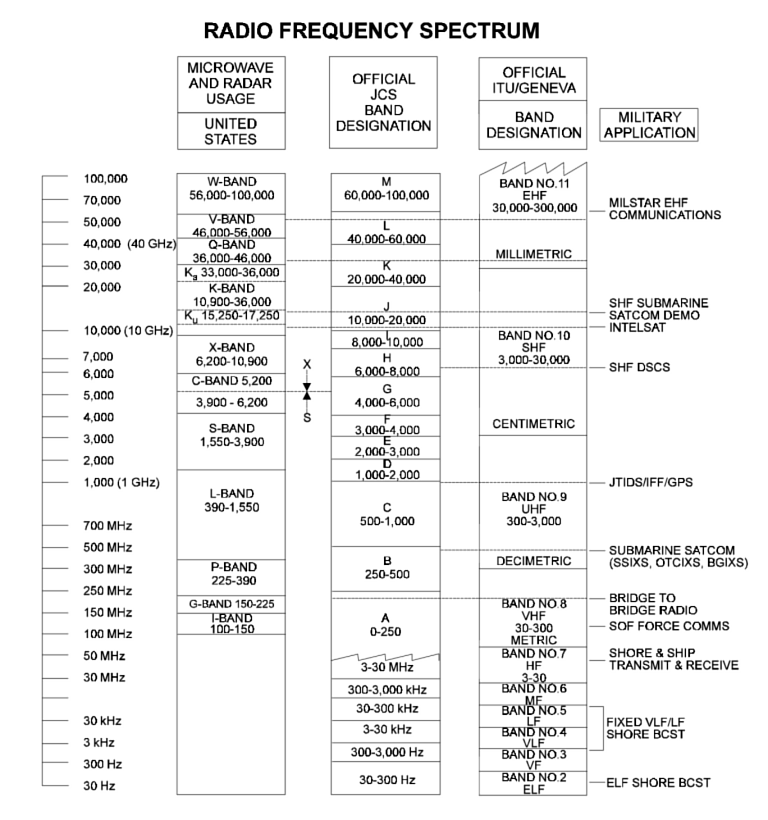 US
DoD
Band
Allocation
Chart
|
||||||||||||||||||||||||||||||||||||||||||||||||||||||||
References
|
||||||||||||||||||||||||||||||||||||||||||||||||||||||||
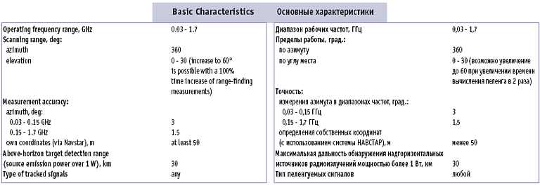
Former WarPac Systems Topaz Kolchuga / Kolchuga M Emitter Locating System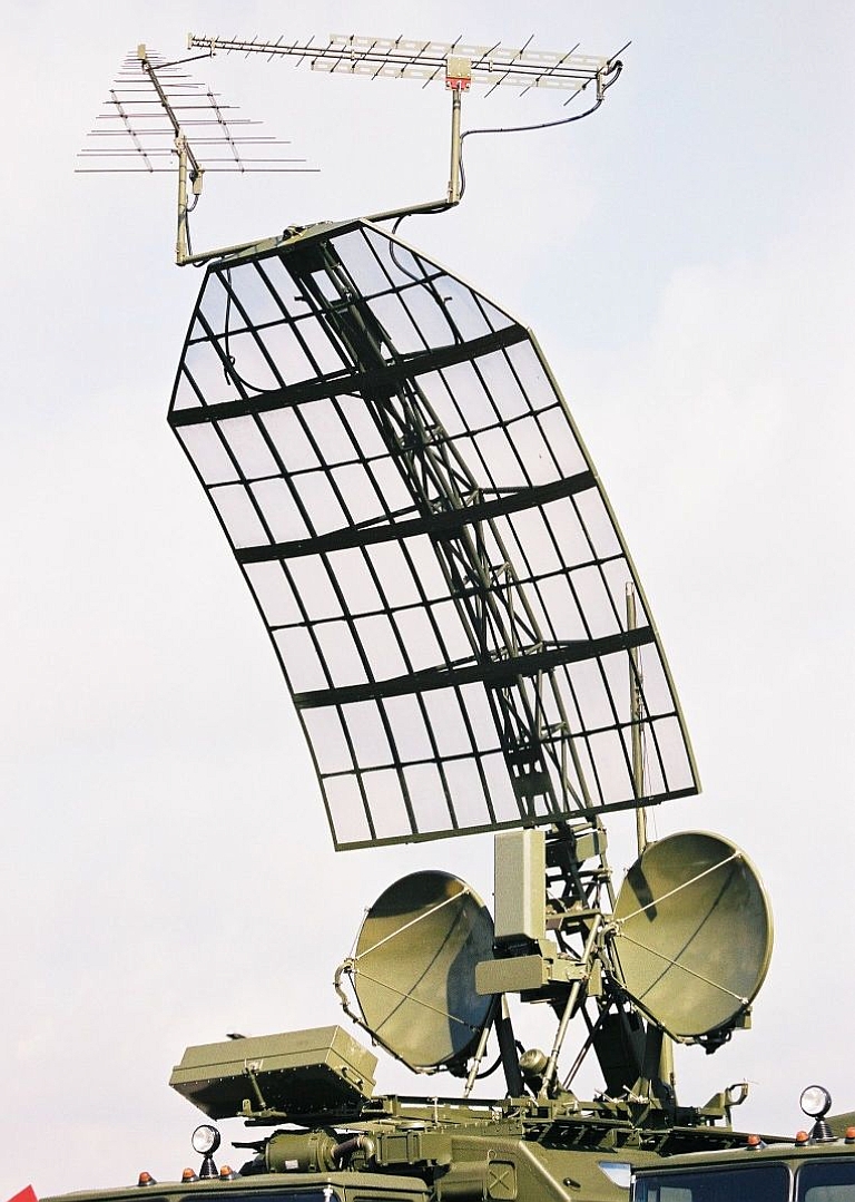 Kolchuga ESM antenna array (Image © Miroslav Gyűrösi). Additional images via Topaz [1], [2]. The Topaz Kolchuga is a long
range direction finding Electronic Support Measures receiver system,
which if networked can provide the functions of an Emitter Locating
System using triangulation and DTOA techniques. The design is claimed
to have been
nominated for a State Science and Engineering Prize. It was developed
during the 1990s by a consortium including the Special Radio Device
Design Bureau public holding company, the Topaz holding company,
the Donetsk National Technical University, the Ukrspetsexport state
company, and the Investment and Technologies Company.
Claimed band coverage extents from 130 MHz (VHF) up to the X/Ku-bands. Claimed sensitivity is -110dBW to - 155 dBW. Track capability is claimed to be 32 concurrent targets. The Kolchuga is also claimed to combine DF techniques with DTOA techniques. The latter will be limited in angular extent to targets which fall into the mainlobes of the respective antenna components for the band in question. The sale of four systems to the PRC has been reported. There is ongoing speculation that the system has been supplied to Iran but no validation to date. 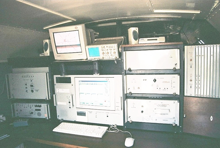 Kolchuga ESM console (Image © Miroslav Gyűrösi). 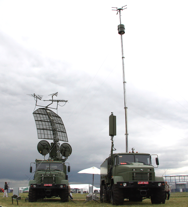 Kolchuga
on
display
at MAKS 2009. Below, note the revised operator station (©
2009
Vitaliy
V.
Kuzmin).
 |
||||||||||||||||||||||||||||||||||||||||||||||||||||||||
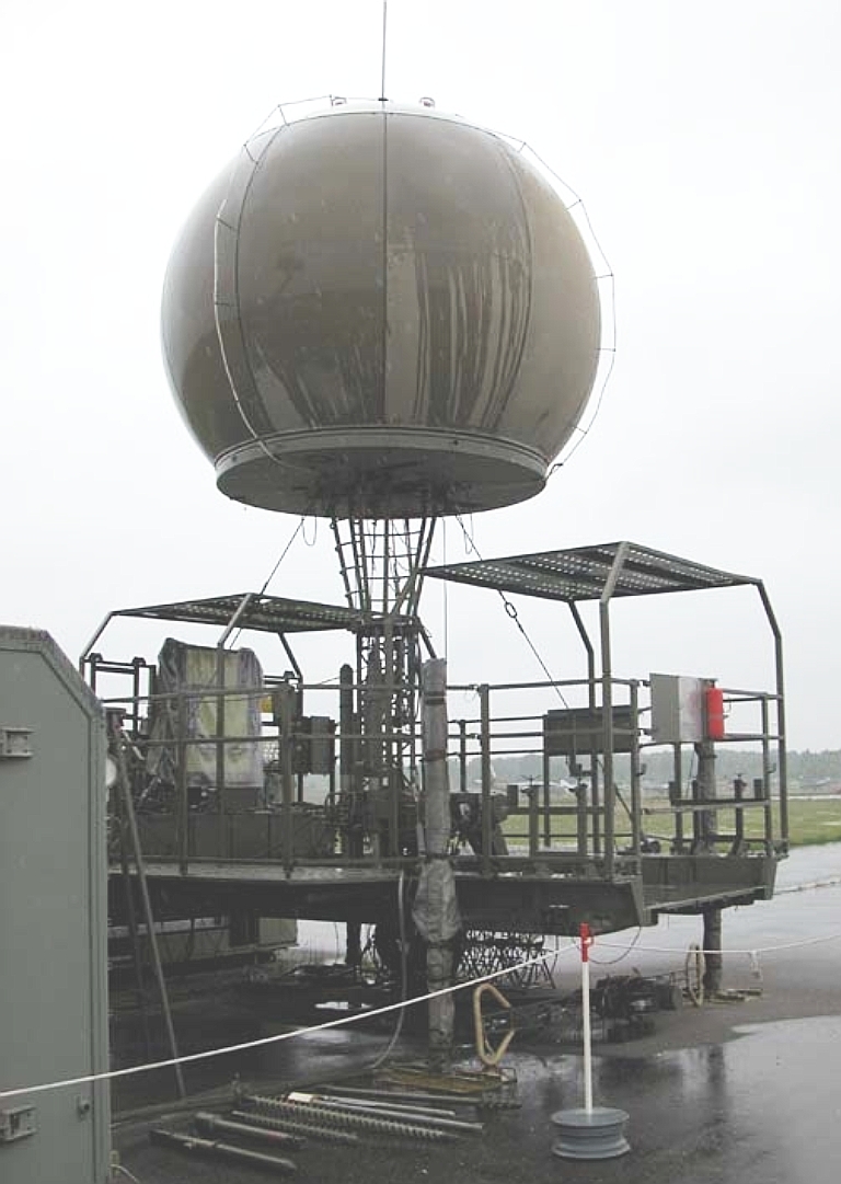
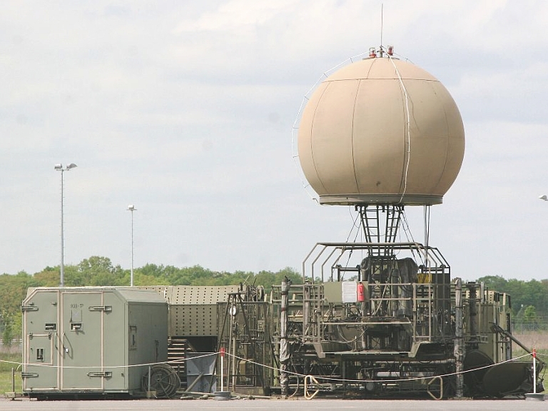 Semimobile
Ramona
/
Soft
Ball
ELS variant of the DDR NVA
at Gatow AFB (Images © Miroslav Gyűrösi). Additional image [1].
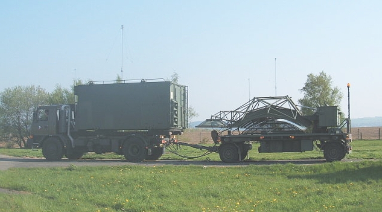
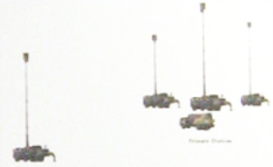
 The Ramona was deployed first
in 1979, as a replacement for the PRP-1 Kopac DTOA ELS which was
developed during
the 1960s, and retired in the late 1990s. It was superceded in
production by the mobile KRTP-86 Tamara. The Ramona system was built in
a semimobile configuration, either on a ground based platform or 25
metre tethered lattice mast. The mast mounted variant weighed in total
160 tonnes, and was carried by no less than thirteen Tatra 138/148 10
tonne 6x6 trucks. The spherical radome housed the receivers and
datalink transceivers required to operate three or more stations.
Deployment of the system on site takes 12 hours.
Band coverage was 1 to 8 GHz, with the primary application in locating and tracking airborne IFF/SSR transponders and TACAN installations. Twenty targets could be tracked concurrently. The Ramona was regarded to be complicated and troublesome to deploy, factors which strongly influenced the design of the subsequent Tamara. Seventeen baseline KRTP-81 systems were built, 14 exported to the Soviet Union, 1 to the DDR, 1 to Syria, and 1 deployed by the CSLA. Fifteen improved KRTP-81M systems were built, the Soviets buying 10, Syria 3 and the CSLA deploying 2 systems. 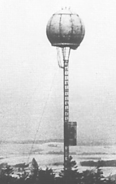 Mast
mounted
Ramona
ELS variant of the CSLA during the Cold War.
|
||||||||||||||||||||||||||||||||||||||||||||||||||||||||
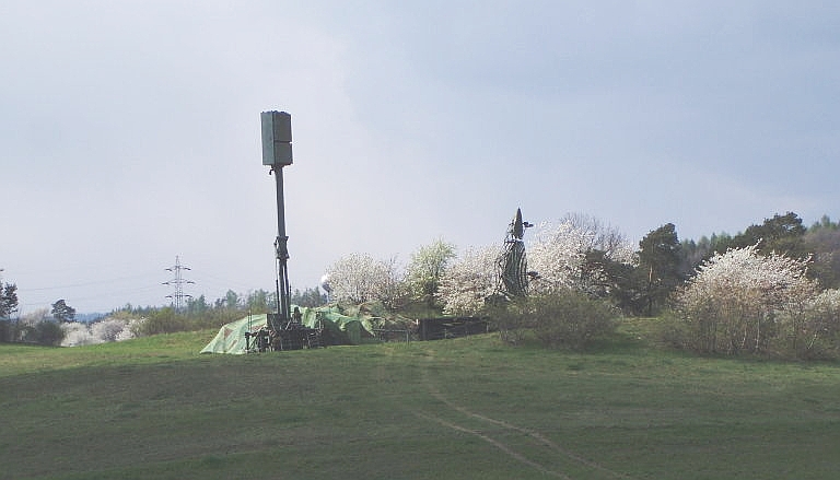
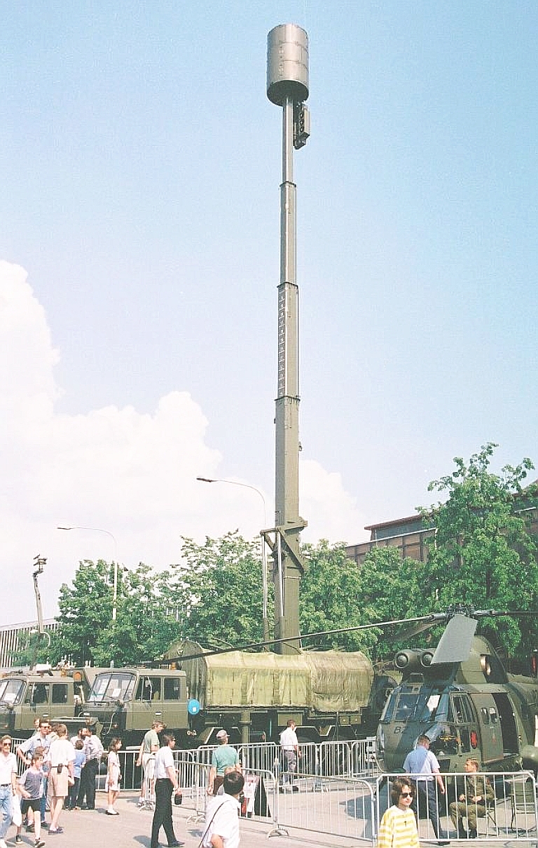
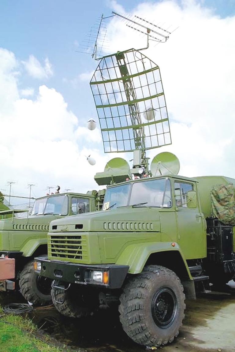
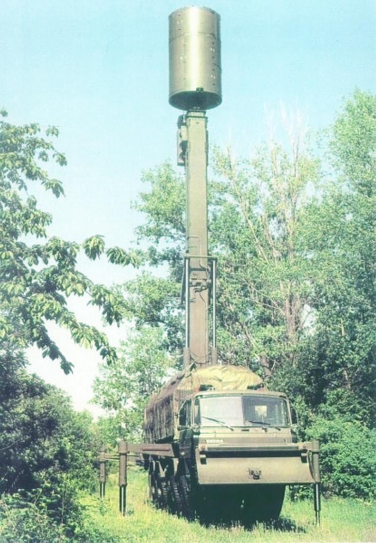
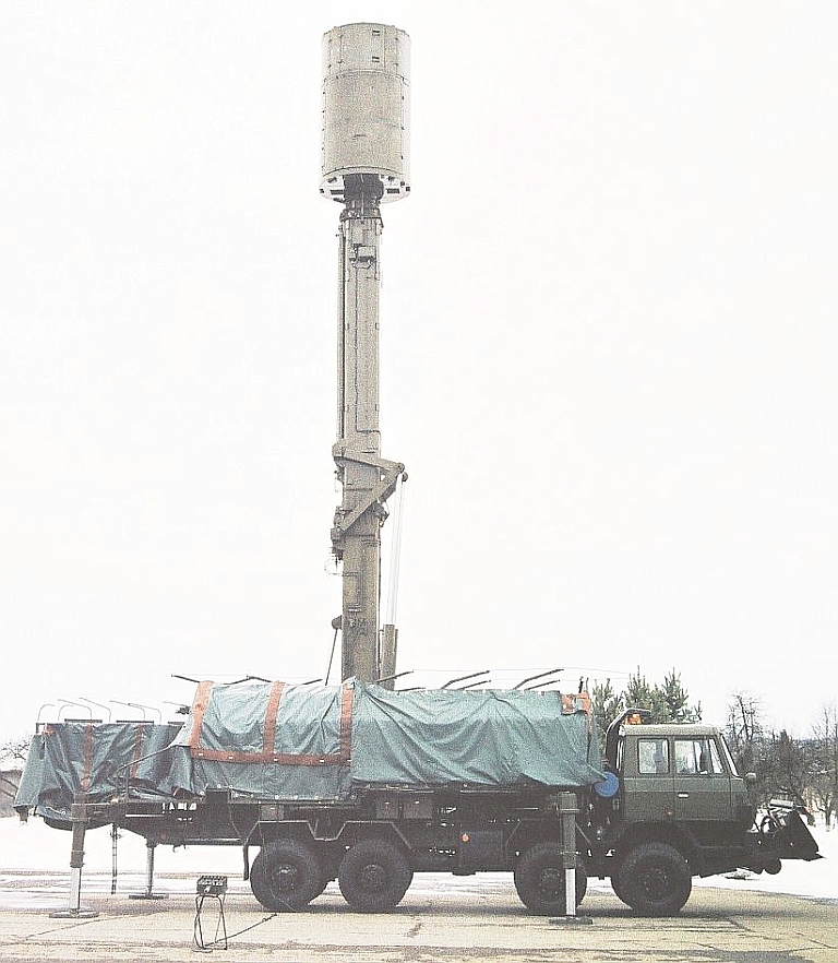 Early KRTP-86 Tamara ELS of the PVO-S
deployed with partially elevated mast (Image ©
Miroslav Gyűrösi).
Additional image [1].
The KRTP-84 Tamara was an
evolution of the Ramona, designed with high mobility and rapid
deployment as a priority. Testing of prototypes began in 1983, followed
by state trials and certification in 1987. A single system is carried
by eight Tatra 815 8x8 trucks (Equivalent to the MAZ-543), comprising
three RS-AJ/M receiver systems with telescoping masts, and a mix of
RS-KB hardware containers, RS-KM signal processing equipment container
and a ZZP-5 command van. The mast mounted RS-AJ/M can elevate to 8.5,
12.5 or 25 metres AGL and can operate at wind strengths below 60 knots,
with a structural limit of 100 knots. The cylindrical antenna radome
houses the receiver equipment and datalink transceivers for networking
the stations. In a typical deployment the receivers are stationed at
distances of 5 to 20 NMI.
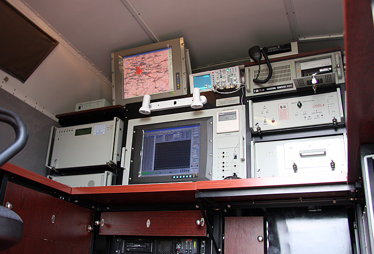
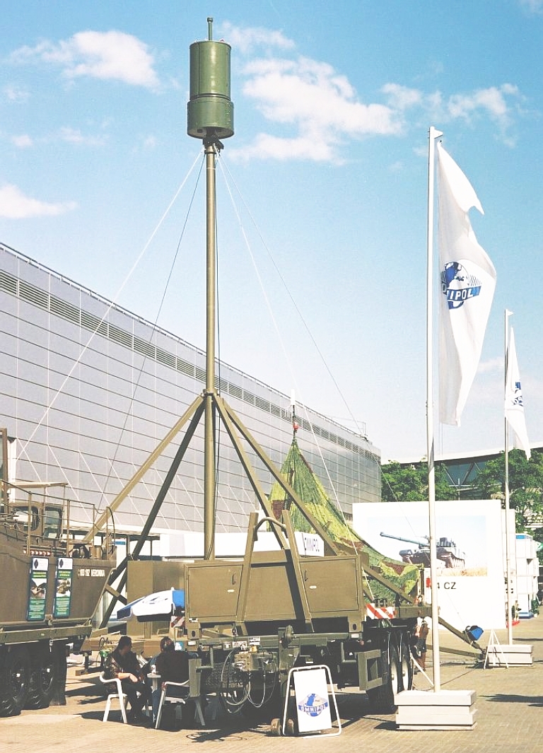
Cited band coverage is 820 MHz to 18 GHz. Design objectives included the tracking of the F-15 at 200 NMI and F-16 at 215 NMI, with the cited range limit being 240 NMI and limited primarily by the curvature of the earth. Russian sources claim that 72 targets can be tracked within a 100° angular sector, these including emitting JTIDS/Link-16 terminals. In 1991 the baseline KRTP-86 was superceded in production by improved the KRTP-91 Tamara-M. Russian sources claim that 23 Tamara and Tamara M systems were built before production switched to the Vera series. Of these, the USSR/Russia acquired 15 Tamara systems and 4 Tamara-M systems, the CSLA 4 Tamara M systems, the GDR NVA one Tamara system, with claims that the US acquired two systems via Oman. KRTP-91
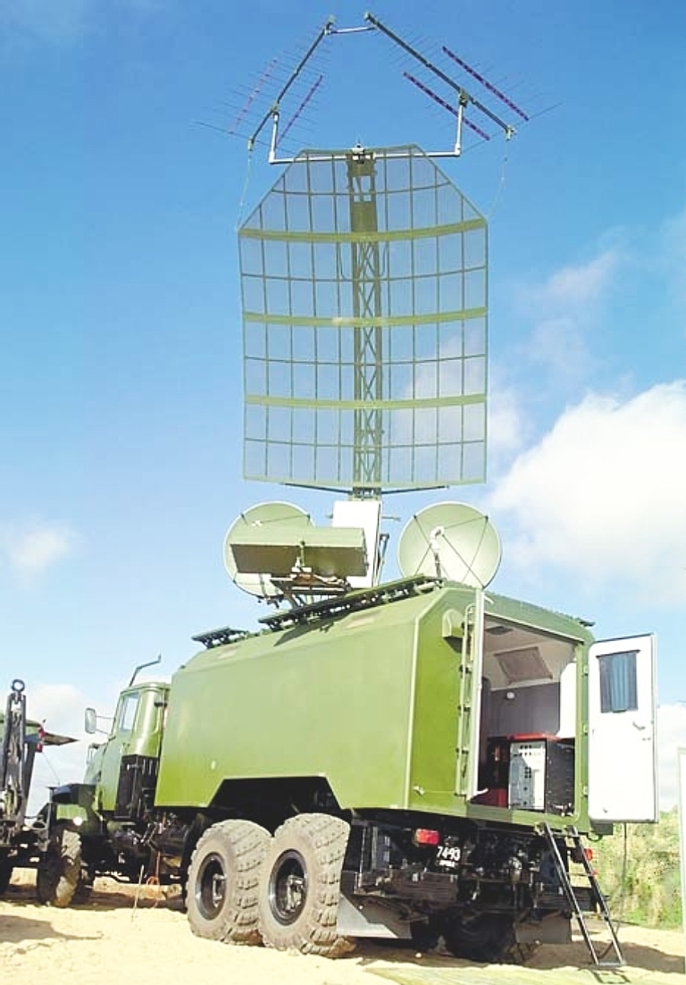
Tamara
with
antenna fully deployed (Image © Miroslav
Gyűrösi).
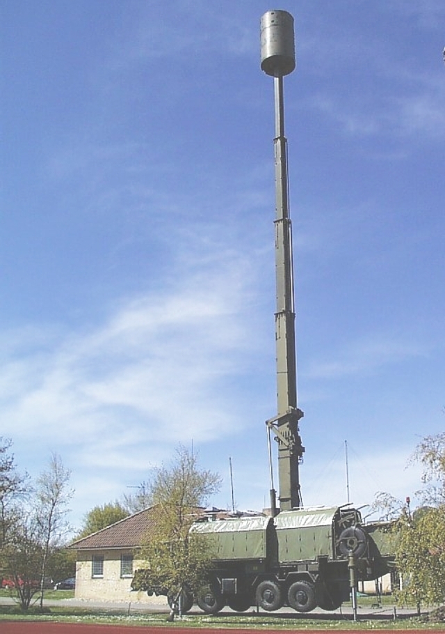 Tamara ELS of the DDR NVA deployed with mast fully elevated. 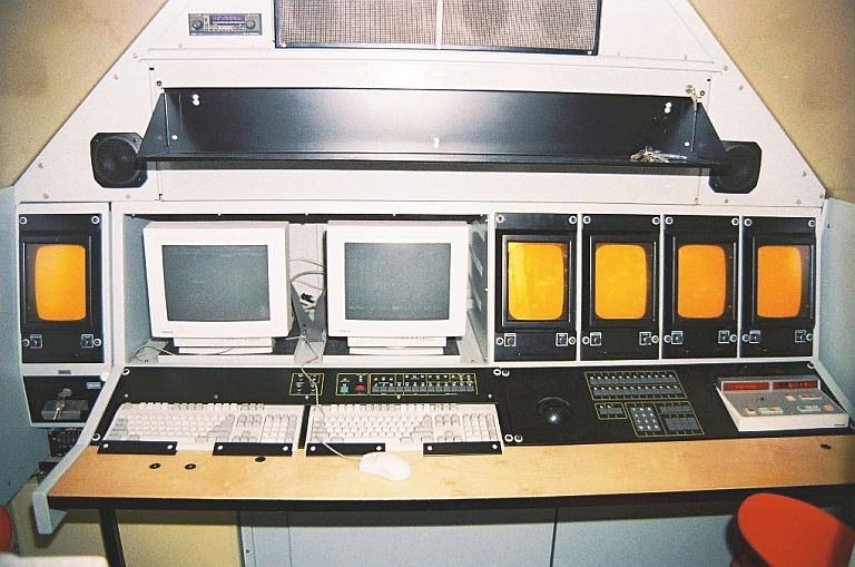 KRTP-91 Tamara console (Image © Miroslav Gyűrösi). 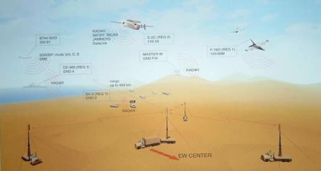 Tamara Concept of Operations. ERA KRTP-96M4 - BORAP Emitter Locating System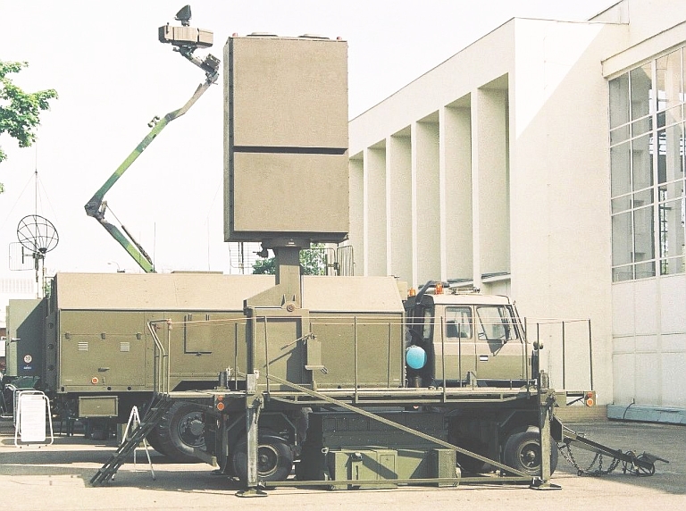 The KRTP-96 series are a follow-on design to the KRTP-91 Tamara series, using a much larger antenna package, and achieving IOC with Czech Army units in 1999. The system has a DF capability and is typically deployed in pairs, providing coverage over a 120 degree angular sector. Frequency coverage is L-Band throught to Ku-band. The system can be deployed in ~1 hr. 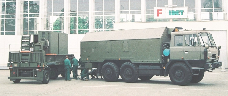 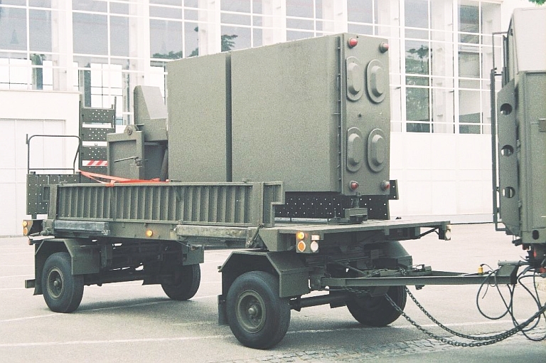 KRTP-96 BORAP ELS antenna stowed (Image © Miroslav Gyűrösi). 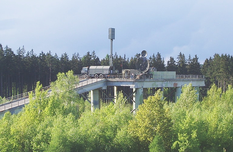 Deployed ERA KRTP-96 BORAP ELS of the 531st Passive
Surveillance Systems Battalion of the Czech Army (Czech Army image).
 Deployed ERA KRTP-96 BORAP ELS of the 531st Passive Surveillance Systems Battalion of the Czech Army (Czech
Army image).
 ERA Vera E Emitter Locating System. The Vera E equipment displayed to date has been installed on trailers rather than the robust truck mounted mast system of the Tamara series (Image © Miroslav Gyűrösi). The post Cold War Vera systems are improved derivatives of the Tamara, and have not proven particularly successful in the market, in a large part due to the fact that the clients most interested in the product are not part of the Western alliance. China was granted export licences in 2004 for six Vera-E systems, which were revoked after pressure was brought to bear by the US State Department. There are reports that Malaysia, Vietnam, Pakistan and Egypt were interested in acquiring the system. The Czech Army has acquired one system, the US DoD one system, and the Estonians one system. 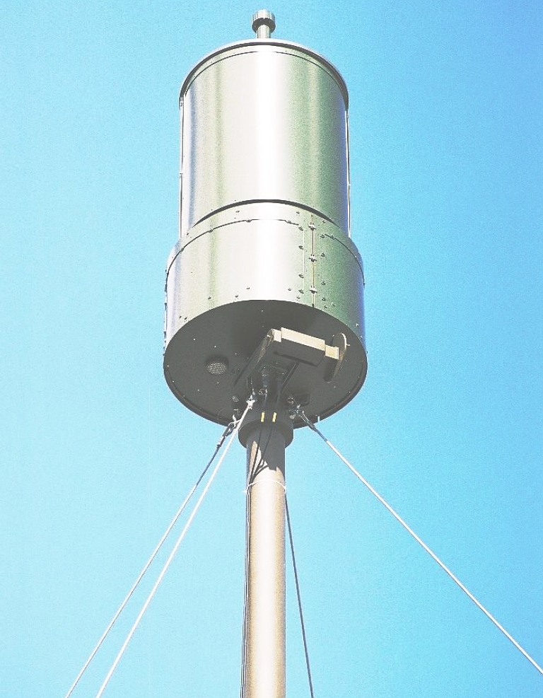 ERA Vera E Emitter Locating System antenna package (Image © Miroslav Gyűrösi). 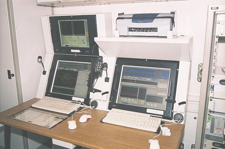 ERA Vera SM of the 531st Passive Surveillance Systems Battalion of the Czech Army (Czech Army image). 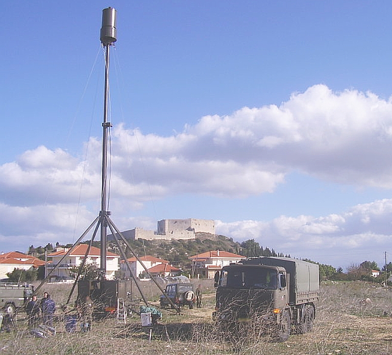 ERA Vera SM of the 531st
Passive Surveillance Systems Battalion of the Czech Army (Czech
Army image).
|
||||||||||||||||||||||||||||||||||||||||||||||||||||||||
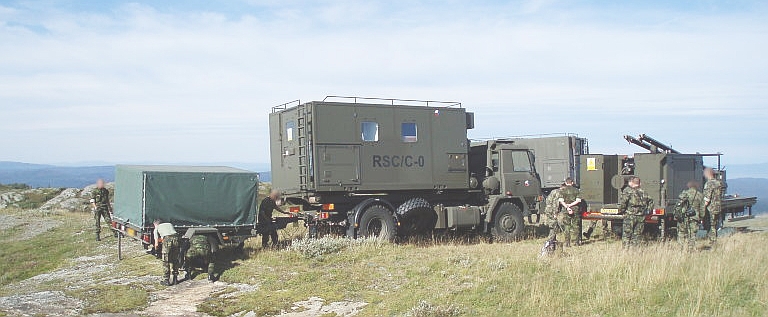
RAMET / VTÚO
SDD Stanice
Dalekého Dosahu (Long Range ESM
Station)
|
||||||||||||||||||||||||||||||||||||||||||||||||||||||||
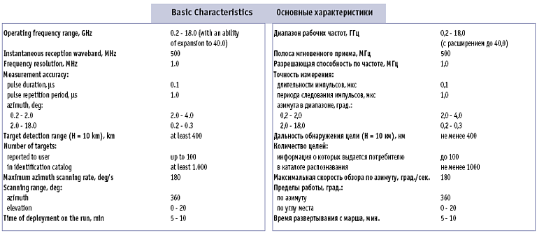
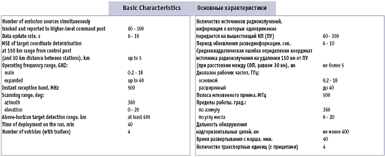
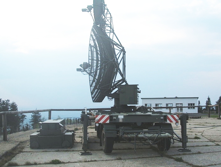
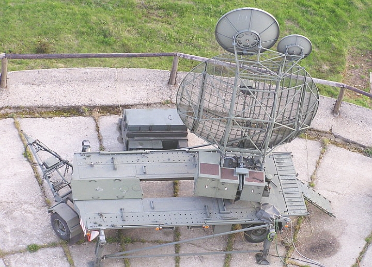
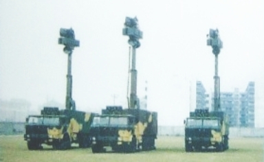
Russian Systems 85V6 Vega / Orion ELINT System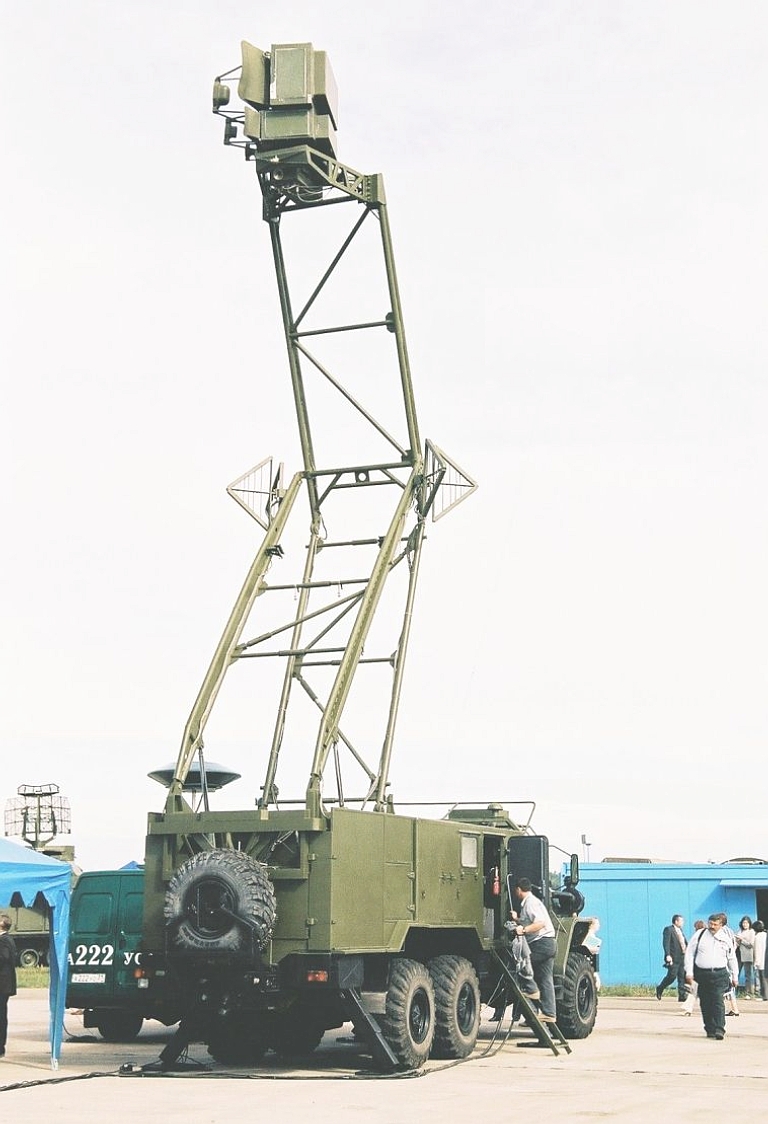 Deployed 85V6 Vega / Orion ELINT System (Image © Miroslav Gyűrösi). 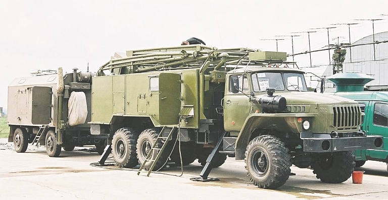 Stowed 85V6 Vega / Orion ELINT System (Image © Miroslav Gyűrösi). 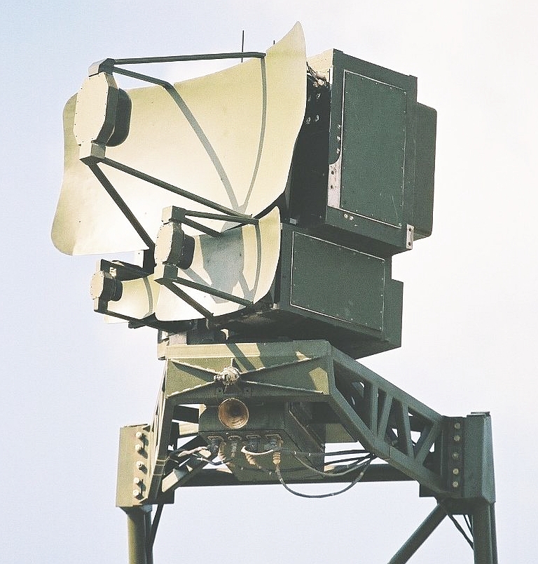 Antenna package on the 85V6 Vega / Orion ELINT System (Image © Miroslav Gyűrösi). 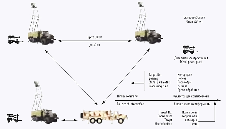
    |
||||||||||||||||||||||||||||||||||||||||||||||||||||||||
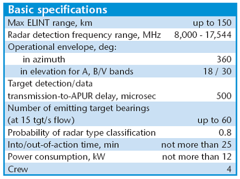
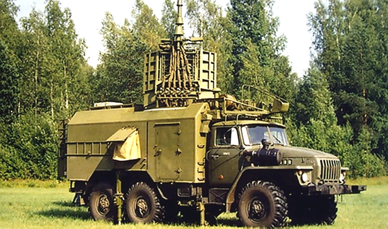
Kvant 1L222 Avtobaza ELINT System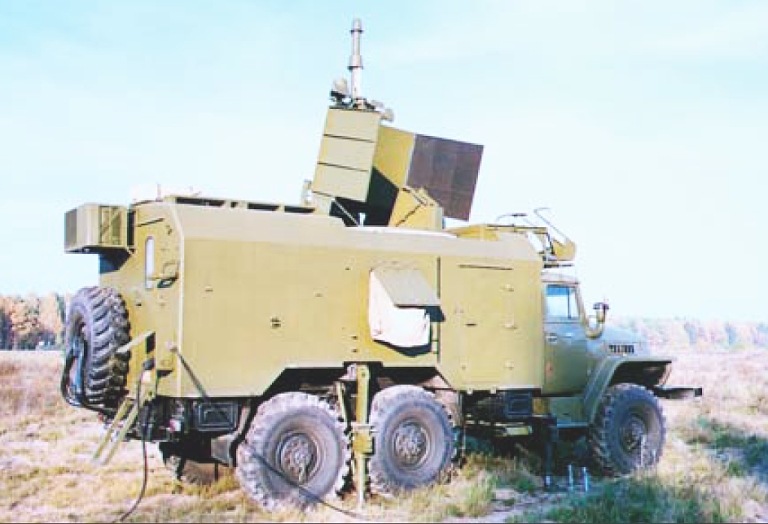 Rosoboronexport
Description
(Cite):
The Avtobaza ELINT system is
designed to detect airborne side-looking radars, air-toground
fire-control radars and low-altitude flight control radars, as well as
to provide intelligence data for the 1L125M APUR.
Composition
  |
||||||||||||||||||||||||||||||||||||||||||||||||||||||||
Lantan/Almaz-Antey Valeria E ELINT and Emitter Locating SystemRussian sources have reported the development of the Valeria E which appears to be Russian designed and built replacement for the Czechoslovak KRTP-86/91 Tamara series of emitter locating systems. To date no imagery of the antenna system and vehicles has been published. The system is intended to detect, track and identify airborne emitters, including radars and support jamming aircraft, from VHF through to the Ku/Ka bands. A cylindral wideband phased array antenna is employed. Cited Capabilities (Rusarmy.com):
  |
||||||||||||||||||||||||||||||||||||||||||||||||||||||||
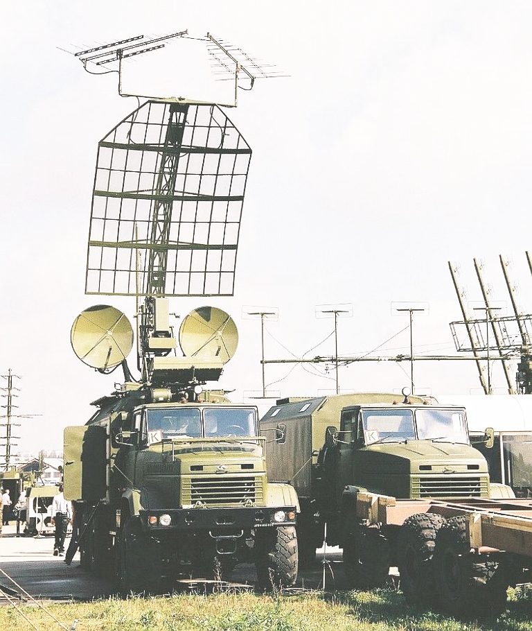
CETC DWL002 Passive Detection System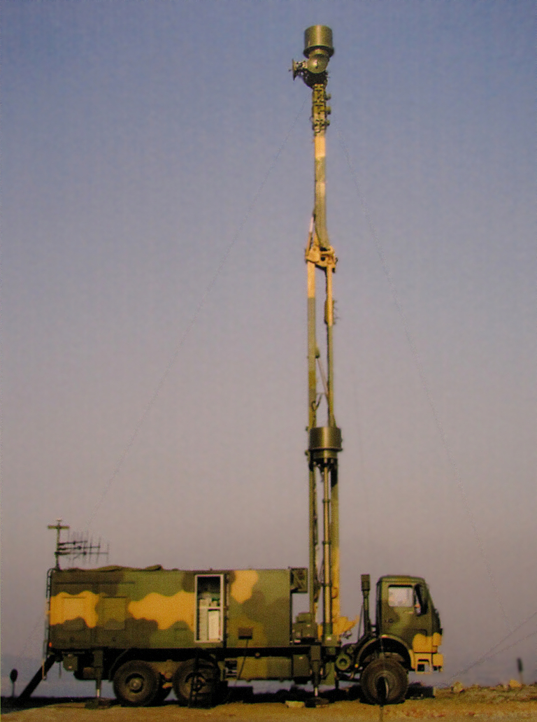 The recently disclosed DWL002 is a modern
and technically sophisticated digital Emitter Locating System,
which builds on ideas employed in the earlier YLC-20 ELS. While design
employs much the same DTOA and Angle Of Arrival [AOA] techniques as the
much older Russian, Ukrainian and Czech ELS systems, the DWL002
introduces an important innovation, which is the use of paired primary
wideband apertures, displaced in elevation. The resulting phase and
time differences between the upper and lower antennas permit
heightfinding, otherwise problematic in earlier single aperture designs.
The primary apertures are housed under cylindrical radomes, in an arrangement similar to the KRTP-91 Tamara and ERA Vera systems. The lower primary aperture is on a telescoping mast, the upper primary aperture on the articulated folding main mast, which employs hydraulic actuators. Below the upper primary aperture is a package of steerable parabolic antennas, likely operating in the upper X-band or Ku-band. These are employed to provide high data rate links between the three or four networked DWL002 systems when deployed. The aft of the equipment container also mounts three Yagi antennas, the purpose of which has not been disclosed. It is most likely that these are employed for datalinking target track data from the networked DWL002 systems to other air defence assets. The system is carried on a North Benz ND1260 (Mercedes-Benz NG 80) 6 x 6 military truck, common to recent radar designs such as the YLC-2V, JY-11B, JYL-1, YLC-18, Type 120, Type 305A and Type 305B. This will result in similar onroad and offroad performance. The strategic significance of the DWL002
is that it is the first DTOA technology ELS which has been designed
from the outset with the intention of providing robust heightfinding
capability when passively tracking an emitting target. The ability to
generate near-realtime or soft realtime 3D target tracks would be
especially valuable in supporting SAM systems like the S-300PMU2 or
HQ-9, as this could be employed to cue the SAM engagement radar very
precisely to the inbound target. Should the accuracy of the ELS be
sufficiently high, it could be employed to generate post-launch
midcourse tracking corrections for outbound SAMs.
The CETC brochure describes the system thus:
“DWL002 Passive Detection System, also called
as
passive
radar, is
mainly used in air-defense or seashore monitoring to perform the
detection to perform the detection and location to airborne, shipborne
or landbased emitters in complex electromagnetic environment and
display the target flight path in real time. The system can also
operate together with active detection system to form a mutual
supplementary surveillance network.
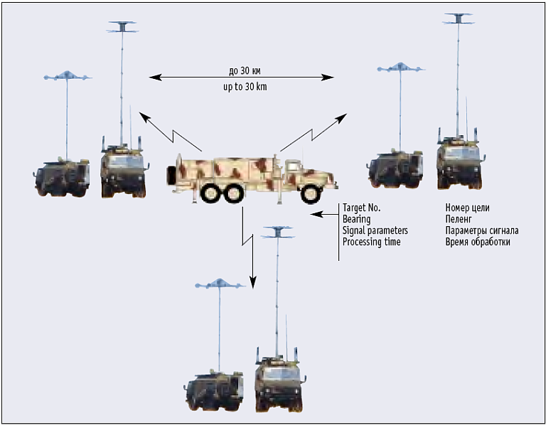
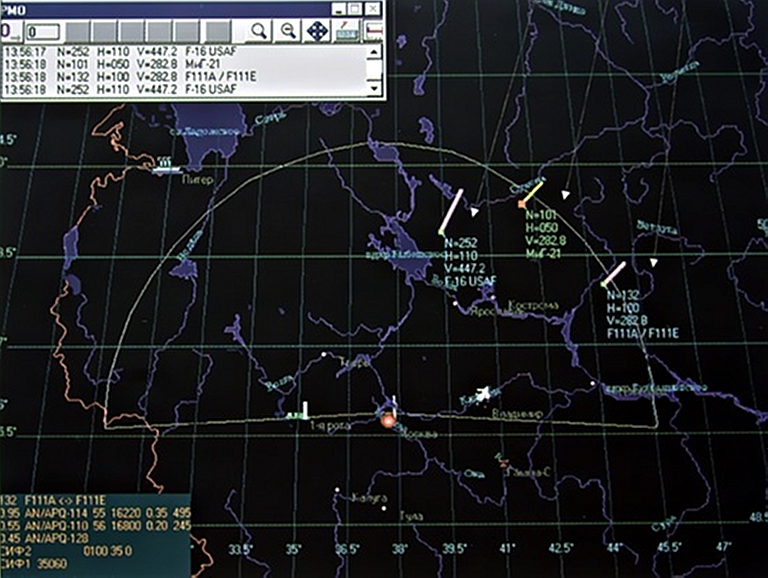
Typical configuration of DVL002 Passive Detection 'system is composed of three reconnaissance stations. One of them serves as master station and the other two as slave stations. The system can be expandable to four station configuration with perfect performance of full spatial coverage and altitude information of air target. Each station is carried by an individual vehicle. Main Functions: * Realtime & Accurate Location and Tracking * Signal Analysis and Identification * Long Range Detection and Early Warning Main Features: * Passive * Real Time * Very Good Mobility DWL002 Passive Detection System is a three station configuration (expandable to four station configuration). Each station. including antenna and power generator. is housed and carried by one vehicle. which ensures the good mobility of the system * Remote Control * Advanced techniques Long base line time difference of arrival (TDOA) location technique combined with AOA: Wideband digitized receiver technique; Multilevel correlation processing technique with good flight track processing result: Automatic set up. Chassis leveling techniques and automatic north calibration technique to ensure fast deployment and flexible operation.” 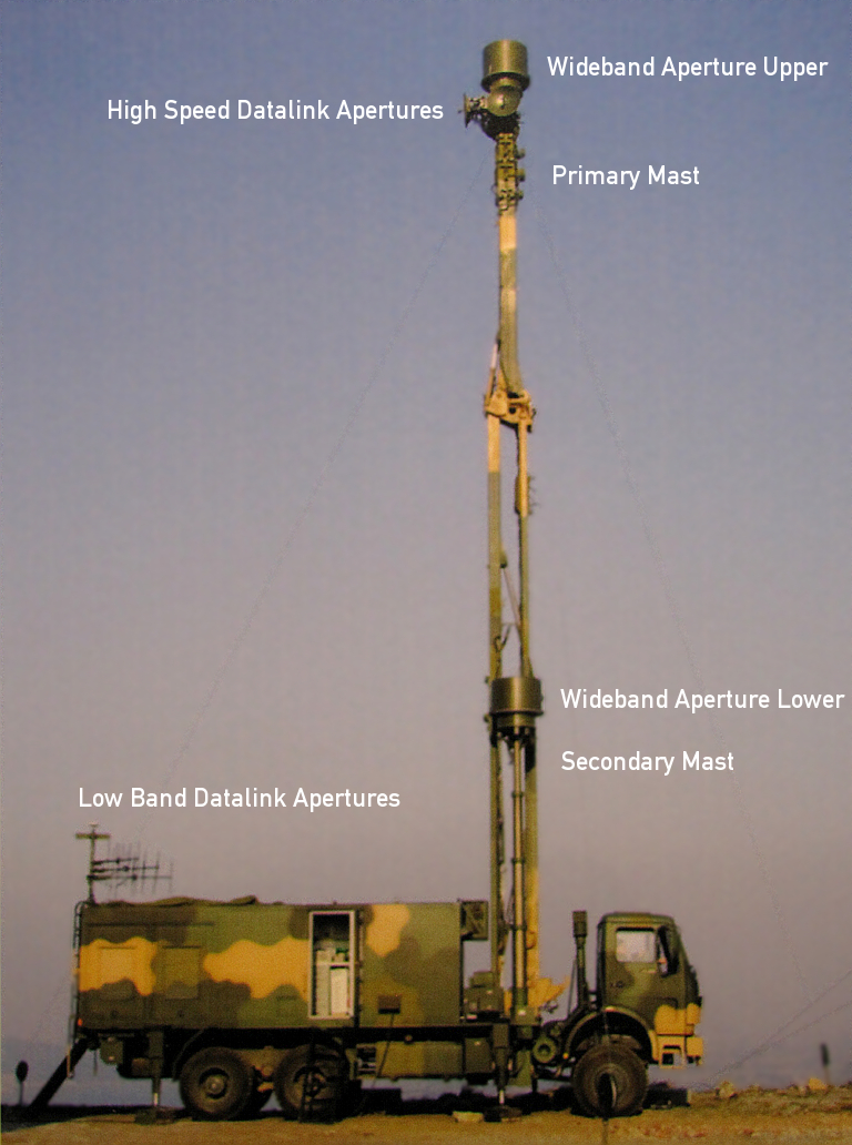 DLW002 antenna arrangement. 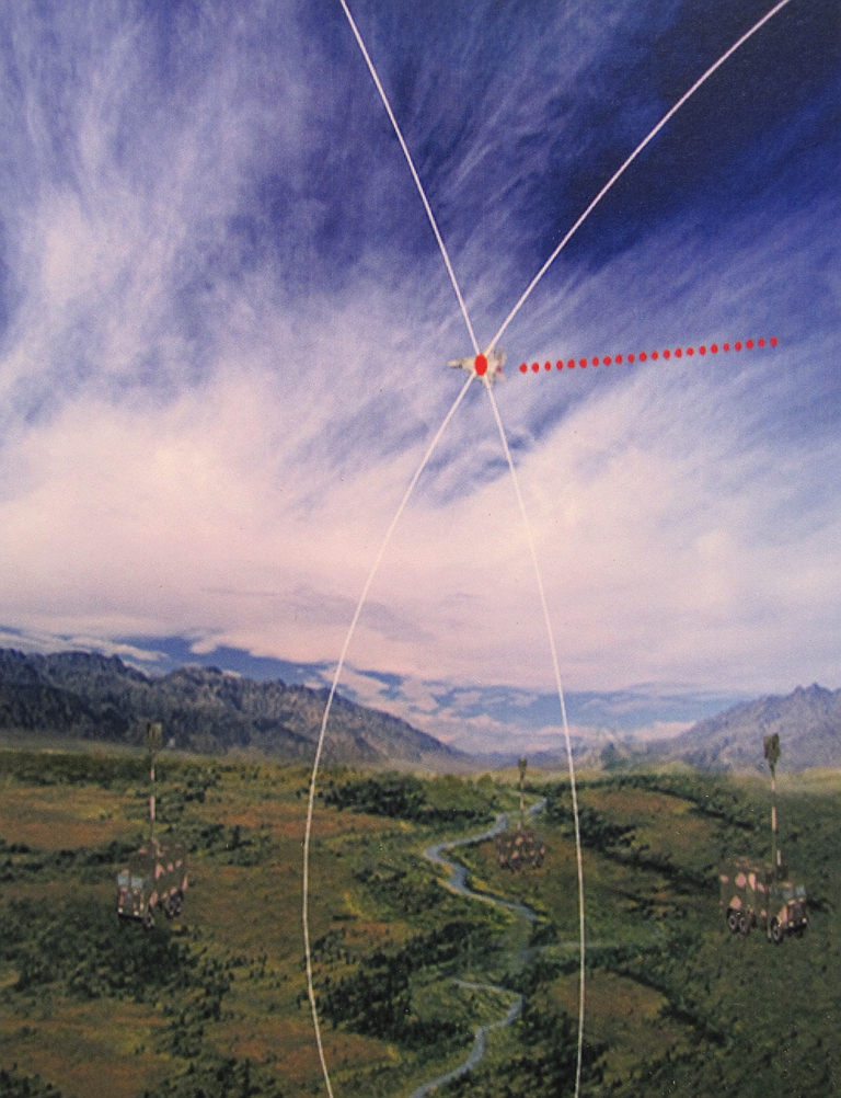 DLW002 CONOPS diagram.  DLW002 console display of target track. CETC YLC-20 Emitter Locating System
The CETC YLC-20 is a DTOA/DF system modelled on the Tamara M (via IASC) The Chinese YLC-20 is
conceptually
based on the KRTP-91 Tamara, but incorporates both precision DF and
DTOA capabilities to locate airborne and surface based emitters.
The only open source material at this time states the YLC-20 is
intended to detect, locate and identify:
Stated band coverage is 380 MHz
to 12
GHz. Deployment time is claimed to be 1
hr, with all system components on 8x8 or 6x6 trucks. At the time of
writing no good quality imagery of production equipment was available
through open
sources. This limits current assessments of the system's capabilities.
It is likely that DTOA techniques are used for target acquisition and
coarse tracking, and DF techniques used for precision tracking, using
DTOA derived coordinates to cue an interferometric DF antenna.
Avaliable material does not state whether a heightfinding capability is
provided, if so this would likely be performed using interferometric
techniques with the DF subsystem. Once better quality imagery of the
antenna arrangement becomes available, a more precise definition of
capabilities and limitations will be possible.
It is likely that much of the YLC-20 design is based on documentation acquired during the abortive attempt to procure six Czech Vera E DTOA ELS systems. The YLC-20 was first disclosed in 2006.  We have yet to see hard evidence that the
PLA is integrating the YLC-20 or Kolchuga M with its S-300PMU/PMU1/PMU2
SAM batteries. That is however not a technically difficult task to
perform and given recent Chinese writings on the use of VHF radar to
provide midcourse guidance for SAMs, something we can be certain the
PLA is planning. The principal risk which arises is that emissions from
any network antennas on combat aircraft which can be detected by more
than two DTOA or DTOA/DF ELS would permit passive tracking and provide
coordinate data of sufficient accuracy to effect a SAM shot - or vector
a fighter (Author).
 |
||||||||||||||||||||||||||||||||||||||||||||||||||||||||
Differential Time Of Arrival Emitter Locating SystemsDTOA systems make use of three
or four widely displaced receiver stations which employ a synchronised
high precision clock. All received signals, such as radar pulse trains,
IFF emissions, network or datalink packets, etc are identified, sorted,
and timestamped, and the collected data relayed to a central processing
site, such as a van. What a TDOA system exploits is the fact that the
geographical location of any emitter which produces a specific
difference in time of arrival to a pair of receivers will fall along a
hyperbolic curve termed an "iso-chrone" (curve of like time).
With two receivers the observer knows only that the location of the emitter falls somewhere along a curve. With three or more receivers, the observer knows the emitter falls somewhere along several curves. The points where these intersect is where the emitter can be found.  Technical Report APA-TR-2008-0503 |
||||||||||||||||||||||||||||||||||||||||||||||||||||||||
|
|||||||||||||
|
|
|
|
|
|
|
|
||||||
|
|
|
|
|
|
|
|
||||||
|
|||||||||||||
| Artwork, graphic design, layout and text © 2004 - 2014 Carlo Kopp; Text © 2004 - 2014 Peter Goon; All rights reserved. Recommended browsers. Contact webmaster. Site navigation hints. Current hot topics. | |||||||||||||
|
Site Update
Status:
$Revision: 1.753 $
Site History: Notices
and
Updates / NLA Pandora Archive
|
|||||||||||||
|
|
Tweet | Follow @APA_Updates | |||||||||||
|
|
|||||||||||||
|
|
|||||||||||||


