|
||||||||||||||||||||||
 |
||||||||||||||||||||||
 |
 |
 |
 |
 |
 |
 |
 |
|||||||||||||||
 |
 |
 |

|
 |
 |
 |
 |
|||||||||||||||
 [Click for more ...]") |
||||||||||||||||||||||
| Last Updated: Mon Jan 27 11:18:09 UTC 2014 | ||||||||||||||||||||||
|
||||||||||||||||||||||
|
||||||||||||||||||||||
|
||||||||||||||||||||||
|
|
|
|
|
|
|
|
|||||||||||||||
|
|
|
|
|
|
|
|
|||||||||||||||
|
||||||||||||||||||||||
| Last Updated: Mon Jan 27 11:18:09 UTC 2014 | ||||||||||||||||||||||
|
||||||||||||||||||||||
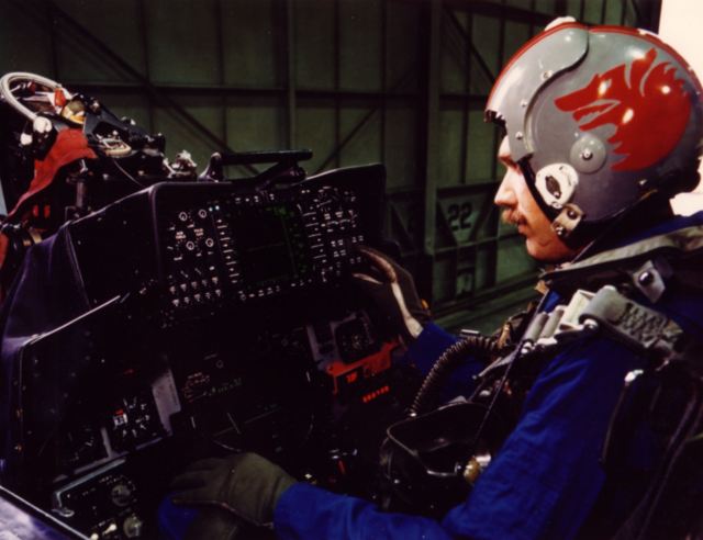
| THE MODERN FIGHTER COCKPIT | |||
|
|||
|
The last thirty years have seen the development of a whole range of weapon and target acquisition systems and each of these have very particular ways of presenting what they have to say. Radar is the most obvious example. From a crude device barely capable of resolving a close target, it has developed to the stage where large volumes of space can be covered, in the presence of clutter and countermeasures, where multiple targets can be tracked and identified. This illustrates the changing demands - thirty years ago the operator would directly interpret the target's behaviour from the returns on his scope - now this becomes near impossible. The conventional cockpit falls short of practically all the requirements given by contemporary aerial warfare. As good as the placement of instruments may be, the pilot must still take his eyes off the target and refocus to the plane of the instrument panel. This, aside from increasing reaction time, gives the enemy an opportunity to make a break for it - a high g turn at that instant may very well put the target out of the field of view. The fact that the information itself must be found on the faces of a number of separate instruments doesn't help, just as interpreting a radar image takes time. One possible solution is carrying a backseater. He can keep a watch for enemy aircraft and work the radar, as in the F-4. In fact, the USMC wants all its F-18s delivered as two-seaters. On the other hand, backseaters come at the expense of fuel, payload/range, reliability, and cost more. The other possible solution, aside from getting oneself shot down, entails presenting all relevant information to the pilot in a manner which will assist him instead of hindering him. If we examine the information in question, we can basically divide it into two groups - critical information and status information. Critical information contains everything vital at a given instant, eg, airspeed, altitude, Mach no, attitude, g-loading, gunnery information, target parameters, etc. Status information covers the things which are looked at only once in a while or only when needed, eg, fuel, ammunition, engine parameters, external stores, ECM, tactical/radar in formation, etc. Each of these groups have their special requirements in presentation. Critical information must be presented in the pilot's field of view, enabling him to concentrate on the external world. The form in which it's displayed must be easy to interpret, to save time and it must be arranged so as not to clutter up the area occupied by the target during gunnery. Status information demands organisation. It must be easily accessible and again uncluttered, to minimise errors in inter pretation. There is nothing worse than staring into a pile of figures which hardly make sense, especially when you're trying to find out what went wrong where. A system displaying status type information must be flexible, to accommodate changes in systems and role.
The Head-Up-Display (HUD) and the Head-Down-Display (HDD) are
both systems designed to satisfy these needs, both were developed over
a
period of time, and both were first designed as part of specialised
weapon systems, prior to their more general application.
Digital
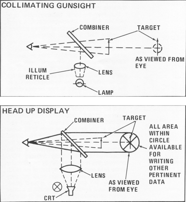
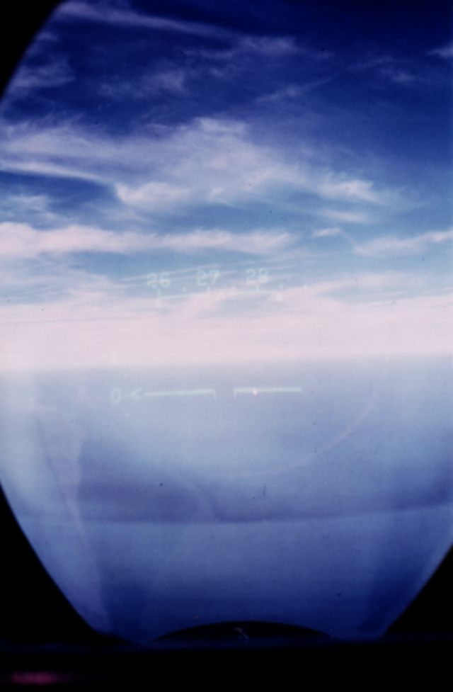
CRT display for AN/AWG-9PSP upgrade in test (Hughes) The HDD The head-down display began its life as a radar display. Towards the end of the '60s the radar began to track several targets at once and the conventional scope was found to be less than ideally suited to the task of displaying alphanumerical, symbolic and numerical information. An alternative was chosen - the CRT, as used in television. (See section on CRTs.) In this application, the HDD displayed information from the weapon systems computer which was tied to the radar and its processing circuitry. Further development required a small, compact computer which would free the HDD from the weapon system and enable it to cover other functions. The micro processor chip satisfied that demand and the '70s saw the HDD take over other tasks. Current applications are wide ranging. HDDs are being used for displaying television type images - typically the FLIR infrared cameras used on the A-7, B-52, A-10 (two-seater), F-18A (attack), or the low light television (LLTV) as tested on the A-10 two-seater. The Hughes TRAM (target recognition and attack multisensor) also uses a HDD to display its imagery. Radar pictures can also be displayed, it is merely a matter of processing electronics to do the job. Symbology, the original task of the HDD, has been complemented with numerical and alphanumerical information, as in the F-18. One of the newer uses to which the HDD/CRT has been put is the displaying of attitude information - direct substitution of the artificial horizon. Other instrument readouts, eg, altitude, heading, airspeed may also be combined in this type of display, giving the pilot, at a glance, all the information he would have to gather from all over the panel. This type of display will dominate the airliner cockpit of the '80s. The most notable current application is the Space Shuttle Orbiter cockpit, which uses a number of CRT displays, both for critical information and systems status information. Reliability is enhanced by the flexibility of the system, as information can be channeled into any of the displays, enabling a faulty display to be simply bypassed. The inherent adaptability of this type of system gives it a great future, as opposed to the conventional way of adding another dial to the panel, which does become a bit difficult to handle when space runs out. Hopefully, there never will be a time when space runs out for CRTs. The HUD The head-up-display is the younger brother of the collimat ing gunsight and, in general, has a lot in common with it. The collimating gunsight superimposes the gunsight reticle, focus ed at infinity, on the target, which is also effectively at infinity. In the HUD, the illuminated reticle is replaced by a CRT, which enables the projection of symbology. The image on the screen of the CRT is collimated (focused at
infinity) by a lens system, after which it is reflected by the
combiner.
The combiner is a plate of partially-reflective (coated) glass,
consequently, it will allow some external light to pass through it and
will also reflect part of the light projected onto it by the lens
system. In this manner, both images, external and projected, can be
viewed simultaneously. Two of the most important factors to be considered in the HUD are its field of view (FOV) and its ability to transmit light, or transmissibility. These factors often conflict with other require ments and, as a result, demand special attention. The instantaneous field of view (IFOV) is the angle of visibility available to the pilot without head motion and is given by the optics and position of the pilot's head. The IFOV decreases with distance from the optics and increases with the diameter of the lens (optics/CRT), therefore the HUD must be as close to the pilot's head as possible. Unfortunately, the distance is a factor given by cockpit configuration, particularly the ejection clearance line, and therefore cannot be changed, leaving the HUD anywhere from 40 to 75 centimetres from the pilot's head. A further loss of FOV can be caused by the combiner supports and windshield/canopy framing. The amount of space available for the optics and CRT are limited and place a further constraint on the HUD's FOV, proving a successful system must be a very good compromise. Transmissibility of the combiner and windshield are another
problem. The thick windshields of modern fighters, placed at fairly
acute angles, transmit only about 60 per cent of the light passing
through them. A combiner with 30 per cent reflectivity will allow about
70 per cent of the light to pass through it, leaving about 40 per cent
of the external object's brightness. Under conditions of marginal
visibility this could very probably make the difference between
spotting
a target and missing it.
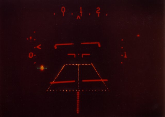
Lowering the reflectivity of the combiner could help, but that, in turn, would demand an increase in CRT brightness, which isn't really desirable, as high brightness CRTs wear out more rapidly, are more prone to failure and often do not provide sharp images. If we succeed in eliminating these problems, another will show its face - sun down the barrel. Sunlight, with its rays close to parallel, can cause difficulty if the HUD's axis becomes aligned with it (sun directly overhead), as it will penetrate the combiner and focus itself on the phosphor (lens to CRT=focal length) and burn it, if exposed for too long. The first visible symptom is a green ball in the middle of the field of view. Optical bandpass filters are a remedy, they limit the amount of sunlight passing through without affecting the imagery. The primary function of the HUD is gunnery, and the flexibility of this device allows for more than the usual stabilisation or target leading. Targets in the FOV can be marked (eg, by boxes, as in the F-15), or their parameters can be displayed, cueing markers can be displayed to assist in lining up with the target and, in the case of ground targets, laser spots can be identified. FLIR and LLTV images can be superimposed over the real world FOV to assist in night/marginal visibility low-level flying. Terrain contours, as detected by the radar, can be displayed, assisting the pilot in terrain masking. The number of target-related functions is extremely large and will grow with time, as radar and image processing techniques improve. The second basic function of the HUD is displaying attitude and flight parameter information, which it can do in very much the same manner as the HDD, the particular form depending on the electronics involved. The HUD is one of the most versatile means of getting
information to the pilot yet devised and its development is far from
over. Direct windshield projection, diffractive optics and advanced
holographics in the future indicate the best is yet to come and we can
look forward to some very capable systems taking their places in the
cockpits of the twenty-first century.
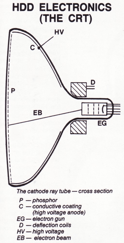
State of the art electronics have been and will be the main factor determining the performance of display systems. At the moment the cathode-ray-tube reigns supreme, having no other serious competition - devices using light-emltting-diode (LED) matrices have been tasted successfully, however, they suffer from two drawbacks, low brightness com bined with bad contrast and insufficient density of picture elements (pixels) [Editor's Note 2005: a problem possibly solved by now emerging Light Emitting Polymer technology]. Though the latter will be overcome In time, the former Is an inherent property of the LED and may yet cause some difficulty. Liquid crystal (LCD) devices are suffering similar pixel density problems as the LED panels but their main drawbacks are low contrast under subdued lighting and slow response. Gas discharge devices have also been tested, pixel density and susceptibility to vibrations are the main obstacles. The CRT, in spite of its age, is still holding its ground. The cathode ray tube is a thermionic device, an evacuated tube with a phosphor coated screen, high voltage anode coating and an electron gun (see diagram). The electron gun (EG) serves as a source for the cathode ray, a beam of accelerated electrons. Electrons are emitted from an electrically heated cathode within the gun and then accelerated and focused into a narrow beam. The beam, upon leaving the gun, is deflected and finally accelerated, by high voltage, until it hits the phosphor screen P. The phosphor absorbs the kinetic energy of the electrons and re-radiates it as visible light. By deflecting the beam we can draw images on the face of the CRT, by controlling the number of electrons in the beam we can vary its brightness. The high voltage used for the final accelera tion is usually of the order of thousands to ten thousands of volts, depending on the particular type of tube. It is applied to the conductive graphite coating inside the tube and is usually generated by a special high voltage power source. Beam deflection can be achieved by a magnetic or electric field, in practice electrostatic deflection is usually chosen for its versatility. The colour and brightness of the image depend on the phosphor used - several colours may be used, if the tube is of the beam penetration type these will be layered on top of each other, colour being given by beam acceleration. If the tube is of the mask type it will have a gun per colour and a perforated mask in front of the screen, the phosphor elements, one per colour, grouped at the perforations. A detailed explanation is beyond the scope of this article, suffice to say that primary colours can be mixed and therefore most of the colour range can be covered. The last point to be examined is that of how the image is drawn. In principle, there are two systems, scanning the whole face of the tube in lines and creating images by changing the brightness of the line or by tracing the image with a full brightness beam. The former system, as used in TV, displays radar or IR/TV pictures best, the latter is used for symbology, typically in HUD applications. The CRT, due to its simplicity and good performance, will
remain the most common HDD system for quite some time, until a worthy
successor is found. 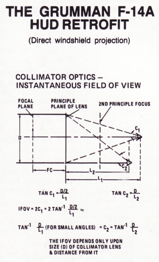 The F-14 Tomcat is an Impressive fighter, In spite of its age, and will continue to be a formidable adversary for some time. Its performance will get a boost with a planned F101DFE engine retrofit and an uprated AIM-54C Phoenix will also have Its effect on overall system performance. What may not be commonly known, Is the fact that the F-14 has already undergone one important redesign and retrofit, namely that of the HUD system. The original F-14 HUD was a typical example of the conventional approach in HUD design, as a result it suffered several major deficiencies. The combiner glass was placed at an angle of 3.6 degrees relative to the windshield, the position was given by the configuration of the cockpit and could not be altered. This resulted in multiple reflections (ghost images) of the
HUD symbology and of external bright lights (eg, runway lights). This
was complicated by further reflections from an electrically conductive
heating layer within the windshield itself, Grumman engineers quickly
eliminated this second source of reflections by removing the conductive
layer, but this resulted in more light passing through the windshield
which increased the brightness of the existing ghost images, making
them
more annoying.
It was essential that all ghosting be eliminated and the design team decided on a novel solution to achieve this goal. The original combiner was removed, its function taken over by the windshield itself. To achieve this it was necessary to modify the optics, the seemingly simple solution of rotating the optics to compensate for the angular difference between the combiner and windshield being insufficient, because the resulting image was out of the pilot's FOV. Further changes involved the windshield, it was thickened by
1.25 cm in order to increase the FOV and eliminate any possible errors
due to bulging under pressurisation or aerodynamic loading.
Grumman
images. Sun-down-the-barrel became more of a problem, with the improvement in light transmission and it was countered with an additional optical filter, a circular polariser. The last major problem to be overcome was the alignment of the HUD to the aircraft's axes, the original combiner glass adjustment being impossible. "Hard mounts" were used, enabling the replacement of the unit without realignment. The mounts on the aircraft are permanently aligned during production, just as the optics are aligned to their mounts during manufacture. The result is a HUD system with perform ance far better than the original design. The absence of any combiner support structure improves the pilot's general FOV and also assists in maintenance, as there is far better access to the optics and front of the cockpit. Reliability is enhanced by the simplicity of the system. The only real disadvantage to be considered is the slightly reduced FOV, however, this is a factor given by the geometry of the F-14 cockpit and is no fault of the HUD. The windshield projection HUD will very probably find applications in ground attack aircraft, as a flat-armour windshield is a usual design consideration in that class of aircraft.
Up to date, HUD and HDD systems
have generally been designed as a part of a particular weapon system,
eg, a radar or as a unit of their own. This type of approach often
leads
to a piecemeal cockpit layout, where all the advantages the HUD/HDD
combination can offer may not be utilised. The ultimate goal would be
the concentration of all vital information and controls within the
pilot's field of view, In a manner enabling near instant transitions
between mission modes (ground attack to dogfight, radar search-scan to
dogfight, etc).
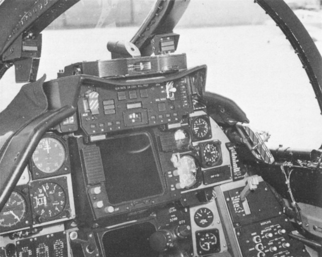
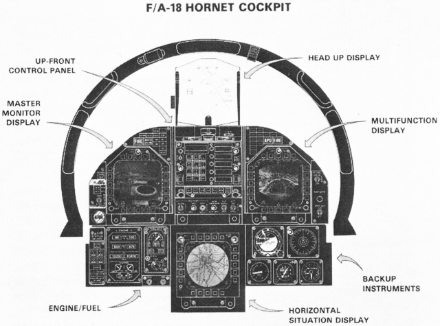
MDC images The F-18 cockpit is currently the closest to that ideal. The requirements for the USN's F-4/A-7 replacement are fairly demanding - the F-18 will have to take on the air superiority/ defence role of the F-4 and the strike role of the dedicated A-7. The F-18 airframe, in spite of enlargement, compared to the F-17, is still short of space, leaving only 40 per cent of the cockpit area of the A-7 or F-4. These factors necessitated the adoption of a new concept. The cockpit of the F-18 features four computer-aided displays, one head-up, the remaining head-down, it also features an upfront control panel (UFC), combining communication and nav/autopilot functions, and a number of automatic weapon/target acquisition controls mounted on the throttle and stick (hands on-throttle-and-stick control concept, devised for dogfighting-HOTAS). The uppermost (see illustration), two HDDs and CRTs, on the left the Master Monitor Display, handling warning/caution, armament, systems status, scratch-pad and FLIR/LLTV functions and on the right the Multifunction Display, which handles radar imagery and is a backup for the MMD. The third HDD is the Horizontal Situation Display, an extremely versatile device which superimposes position/flightpath symbology over a moving map display, as a navigational and tactical aid (Internally the HSD contains a 35 mm projector and a CRT combiner as in a HUD; aside from storing maps, the 35 mm film reel may have hundreds of frames on aircraft systems, tactical data, approach charts, etc). The HSD can also superimpose FLIR/radar imagery over maps, it also functions as a backup to the MMD and MFD. The HUD and HSD are both driven by the MMD or MFD, which, in turn, are driven by two Mission Computers. This structure gives the system enough redundancy to overcome any malfunctions, in the unlikely event of total breakdown, a set of standby instruments is provided. All three HDDs have a common face layout, given by twenty mode programming pushbuttons about their peripheries, this reduces the possibility of error. The HUD displays attitude and flight data aside from its function in weapon delivery and gunnery. A Weapon Selector switch on the stick automatically conditions the radar and HUD to the selected weapon's parameters (Sidewinder/Sparrow/M61), the stick mounted Auto-Lock-on switch allows for boresight, HUD field of view or off-boresight lock-ons. A Target Designator Control, mounted on the throttle, enables quick changes of radar parameters. These three controls allow the pilot to carry out a visual or sensor aided engagement without taking his hands off the controls, a factor which combat pilots should appreciate. The greatest asset of this type of system is its versatility,
as the operating modes of the displays are given by external
programming, the imagery displayed depends on the sensor from which it
was taken. Future applications will highlight these points, as it's
obvious that integrated cockpit systems are here to stay.
The greatest drawback of the conventional HUD Is its inherently small field of view, which is dependent on the diameter of the optics/CRT assembly, as the other factor involved, the distance between the combiner and pilot's eye, is given by the cockpit configuration. The seemingly simple solution of using a collimator/CRT system of a larger diameter Is impractical, If, for no other reason, than the sheer weight and size involved. Diffractive optics are one possible solution to this problem. The physical phenomenon of diffraction has been known for some time, for the purpose of later understanding we shall examine the behaviour of a diffraction grating. A diffraction grating is a plate of transparent material, one side of which is covered by closely spaced, parallel, opaque lines (the spacing is equal to several wavelengths of the light involved). If we shine light through the grating an effect called interference occurs. We can observe this by viewing a monochromatic (of one colour-wavelength) light source through a grating. Aside from the actual image we shall see a series of gradually fading images superimposed on the background. For a horizontal grating, these are above and below the
actual
image. In a diffractive HUD there is no collimating lens, this function
is taken over by the combiner itself. This simplifies the system and
saves weight, while enabling a larger field of view. The combiner of a
diffractive HUD is a curved (spherically) surface; it also has a
diffraction grating type pattern on its surface, which is effectively
invisible. If a monochromatic light source is placed into the optical
focus of the combiner, diffraction will make the combiner reflective to
the source's light (at certain angles) and its curvature will collimate
the light source's image. In this manner the combiner functions as a
collimator to the CRT projected imagery, while remaining transparent to
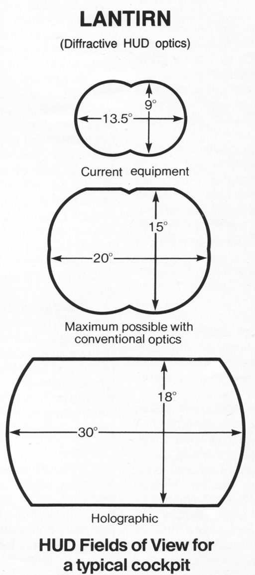
light from the external world. This configuration has a number of advantages over the conventional system. Aside from the FOV, the diffractive system requires less light to achieve equal or better brightness - there are no losses through the partial reflection used in conventional devices, this in turn means lower power CRTs, with all of their advantages. Eliminating the reflectivity of the combiner also means, more light can pass through the combiner, enhancing visibility under marginal conditions. Bad visibility through most of the year is a trademark of the European theatre - this was the main reason behind the USAF's decision to upgrade its F-16 and A-10 forces to an all weather/day-night standard, this by means of a HUD retrofit in conjunction with the fitting of FLIR cameras. The contract for LANTIRN - Low Altitude Navigation Targeting Infra-Red for Night - was awarded to Marconi Avionics. Unfortunately, at this stage, little has been released on the LANTIRN HUD, it will be capable of displaying a wide angle FLIR image in TV raster scan and simultaneously displaying conventional symbology. It appears, from photographs, that the LANTIRN HUD uses a rear projection of the CRT's imagery via a reflecting glass, in which it differs from an earlier "DHUD" tested by Hughes, which used frontal projection. It is quite obvious that the diffractive HUD has a series of advantages over the conventional HUD - it's very probable that diffractive systems will dominate future designs. |
|||
|
|||||||||||||
|
|
|
|
|
|
|
|
||||||
|
|
|
|
|
|
|
|
||||||
|
|||||||||||||
| Artwork, graphic design, layout and text © 2004 - 2014 Carlo Kopp; Text © 2004 - 2014 Peter Goon; All rights reserved. Recommended browsers. Contact webmaster. Site navigation hints. Current hot topics. | |||||||||||||
|
Site Update
Status:
$Revision: 1.753 $
Site History: Notices
and
Updates / NLA Pandora Archive
|
|||||||||||||
|
|
Tweet | Follow @APA_Updates | |||||||||||
|
|
|||||||||||||
|
|
|||||||||||||