|
||||||||||||||||||||||
 |
||||||||||||||||||||||
 |
 |
 |
 |
 |
 |
 |
 |
|||||||||||||||
 |
 |
 |

|
 |
 |
 |
 |
|||||||||||||||
 [Click for more ...]") |
||||||||||||||||||||||
| Last Updated: Mon Jan 27 11:18:09 UTC 2014 | ||||||||||||||||||||||
|
||||||||||||||||||||||
|
||||||||||||||||||||||
|
||||||||||||||||||||||
|
|
|
|
|
|
|
|
|||||||||||||||
|
|
|
|
|
|
|
|
|||||||||||||||
|
||||||||||||||||||||||
| Last Updated: Mon Jan 27 11:18:09 UTC 2014 | ||||||||||||||||||||||
|
||||||||||||||||||||||
| INTEGRATED
FLIGHT AND FIRE CONTROL |
|||
|
|||
|
The last three decades have seen airborne weaponry vastly increase its lethality, both air-to-air and air-to-ground weapons becoming far more accurate and effective. A closer examination will also quickly reveal why this has occurred, as the once dumb weapons became smart weapons, with their own guidance systems, relying less and less on the judgement of the man pressing the trigger on his control column. There was a price to pay, though, the weapons became more and more expensive, they also became susceptible to electronic and other counter-measures. In an environment where switching on one's radar is as good as saying here I am, come and get me. . ., many modern airair and air-ground weapons become less effective than they could be, otherwise. In the event of smaller conflicts, the use of precision guided munitions (PGMs) really presents little of a problem, as adequate stockpiles of guided weapons are readily available, also an enemy who has little experience combating a weapon is also likely to have ineffective, if any, counter-measures. This situation will not persist, particularly in the case of a protracted, large scale conflict. The use of advanced anti-radiation missiles and ECM is likely to limit the use of radar guided weapons. A densely knit air defence network will make offensive support and interdiction missions far more dangerous. Add to that the high cost of PGMs and air-air missiles (AAMs), stocks also running low, and a quite serious situation will develop. The principal cause of this potential problem lies in the fact that the last three decades have really seen little change in weapon delivery techniques - the increase in accuracy is principally due to the weapons acquiring guidance, little attention has been paid to achieving pinpoint accuracy with cheap and unsophisticated munitions, such as the free fall bomb or the cannon shell. The integration of flight and fire control systems promises to do exactly that, at relatively low cost, improving an aircraft's capability in both air-air and airground missions. Figures quoted in connection with the USAF's IFFC/Firefly III program suggest an increase in air-air gunfight lethality of 24:1 and an increase in survivability during air-ground missions of 10:1. Even if these figures are not met in combat, they still represent a useful gain in combat capability and should not be overlooked. A closer look at what IFFC has to offer will convincingly prove that point. Fire Control Systems The principal task of a fire control system is the gathering and processing of information on targets. Virtually all modern aircraft are fitted with one or more sensory systems, radar, FLIR, Laser spot trackers, Low Light TV, Moving Target Indicator radar etc. Target information from one or more sensors is monitored by a Fire Control Computer (FCC), which also monitors the aircraft's own position, via an inertial navigation system or Doppler nav system. Targets are usually identified with IFF and tracked, depending on the sophistication of the system, threat priorities are established. The FCC will then proceed to its main task, computing the appropriate launch or release time and place for the chosen weapon. The computer must have stored information as to the performance of the weapon used, using this and continuously updated information on the relative position of the target with respect to the launch aircraft, it will either issue steering instructions to the pilot or directly steer the aircraft (as in the F-14A Tomcat, where the AWG-9 radar/fire control is actually linked to the fighter's flight controls and will automatically, if commanded, fly the fighter into an optimal missile launch position) into a favourable position for the release or launch of the weapon. Modern fire control systems employ radar and FLIR/Laser equipment for monitoring targets, enabling the attacking of both aerial and ground targets. This was not the case initially, though, as the modern breed evolved from two separate species - the air-air intercept fire control system and the weapon release computer. The former type is best illustrated by the F106A's MA-1 fire control, allowing fully automatic air-air intercepts, the latter type by the various bomb release computers added on to 1960s fighters, as a useful afterthought. It isn't difficult to see that one computer could perform both jobs, one at a time, and this configuration was eventually adopted. In most instances it allows for wings level automatic bomb release and will assist the pilot in gunnery, by providing range and ballistic information to the Head-Up Display (HUD). Flight Control Systems An aircraft's flight control system is the determining factor in enabling a pilot to exploit an aircraft's characteristics. The controls are the vital link between the pilot and the vehicle. In a conventional aircraft, the control surfaces are usually linked to the controls mechanically, with some power assist, to reduce the pilot's workload. This assumes the aircraft is reasonably stable statically (see Artificial Stability, June 1981), which isn't usually the case with modern combat aircraft. The requirements for handling over a very wide range of speeds and angles of attack, combined with the essential demand for a very rapid control response, necessitate the reduction of the aircraft's natural stability. This is, however, more than compensated for by the use of stability augmentation, which results in far better handling characteristics than could be offered by a conventional system. In a modern fighter, inputs from the pilot's controls are fed into a Stability Augmentation System (SAS) computer. This computer is programmed to a control law, a program which determines the aircraft's handling. Upon receipt of a command via the controls, the SAS computer determines the required control surface deflection rate, which it transmits to the actual control surface actuator via the aircraft's fly-by-wire electrical control system. Simultaneously, via means of a set of gyroscopes and accelerometers, the computer monitors the aircraft's actual manoeuvre, and employs this to correct the control deflections it commanded to achieve the exact rate specified by its control law. In this manner, idealised handling characteristics may be built up, as deficiencies in the aircraft's natural behaviour may be cancelled out and desirable characteristics artificially created. (Analogue systems are by nature hardwired to a particular control law, alteration requires physical modification of the electronics, newer digital systems may be altered simply by changing the software in the computer's memory.) Though the pilot may feel that he is flying a nice aircraft, he has actually been removed from the aircraft's control loop (a control loop may be regarded as the flow of information from a source through a system and back to the source, the source may observe the difference between what it fed into the system and what it gets out of the system, it will then use the difference to alter what it feeds into the system to get the desired response; in a conventional aircraft this is represented by the pilot-controls-aircraft-pilot loop) and merely tells the SAS computer what he wants the aircraft to do. Here is where problems tend to arise, as the establishment of the desired control law involves some strong compromises. Rapid response during violent combat manoeuvres dictates a high speed response from the control system upon deflection of the controls (the aircraft must establish the commanded pitch/ roll/yaw rate as fast as possible), but this becomes more than a nuisance during fine tracking of a target, because the pilot will inadvertently overcorrect, leading to an effect called pilotinduced-oscillations (PIO), which may even throw the aircraft out of control in extreme cases. (Actually, the fine tracking process is yet another control loop, where the pilot attempts to align the aircraft's axis with the position of the target.) Fine tracking requires a fairly slow response, in practice a compromise is usually chosen, though another solution exists in the insertion of a non-linear filter between the controls and SAS - it responds to large inputs rapidly and small inputs slowly. As much as an electronic flight control or stability augmentation system has to offer in the way of response and handling improvements, it cannot, on its own, allow the full exploitation of the aircraft's abilities. In order to hit a target. the pilot uses information supplied by the fire control and his own vision to align the aircraft for the release or firing of weapons. and here is where the greatest hindrance can be found - the pilot's own limitations. Take gunnery, for instance. If we set aside things such as gunfiring in high G turns and simply consider a situation where the pilot has to put his cross-hairs (rather circle) on an airborne target, which is trying to evade his gunfire. If both aircraft are travelling at comparable speeds, most of the target's motion is detected as a small change of angular position in the pilot's field of view. What may be a change of position adequate to foil a shot may not be detected until half a second too late. As closing velocities increase, this becomes even worse, as in airground gunnery. Obviously, an experienced pilot can allow for a lot and that's what would make him a good shot, combine this with automatic ranging and lead computing and one can get reasonable results. Providing, of course, that the pilot has adequate time to prepare for a shot, as many gun firing opportunities are not exploited for this reason alone (basically, the pilot must function as a fire control system and estimate where the target will be by the time his gunfire reaches it, mentally plotting the target's path in his FOV. As the target is unpredictable and the pilot's response relatively slow, opportunities will be lost). The solution to this problem is quite simple - employ some sensory system to accurately measure the target's position relative to the aircraft and then use this information to automatically point the aircraft at the target, i.e. integrate the fire control with the flight control system. Integrated Flight and Fire Control Systems The greatest demand which the implementation of an IFFC system will make upon the designer is the precise and rapid measurement of the target's position. Due to the often very close ranges involved in gunnery and the degree of accuracy demanded, air-air radar is inadequate and the choices available are laser/optical or millimetre wave systems, the former more practical at the moment. A laser based system would employ a TV or FLIR camera boresighted with a rangefinding laser and fitted with precision angle measuring equipment to accurately determine the direction the system is pointing in. The system would be fitted with an electronic contrast lock (automatic tracking, see Laser Guidance, September 1981); once the lock is engaged, the system would keep the laser beam aimed at the target, irrespective of the relative motion of the aircraft and target. The angular information derived from the direction of the beam and range information from the laser are sufficient to determine the target's position and this information is then fed into the aircraft's fire control computer (alignment of the laser system to the aircraft is critical, as errors in alignment would defeat the purpose of the system).
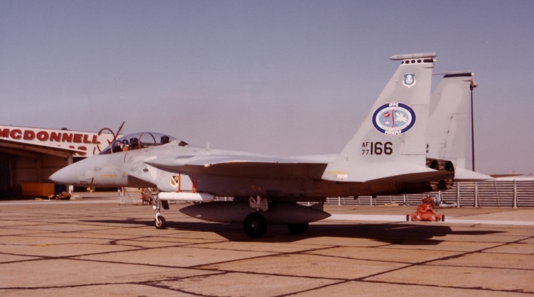
The acquisition and attack manoeuvres flown are preprogrammed into the computer's memory, this allows for automatic evasive manoeuvring during ground attack, as the gun may be fired accurately or bombs released while the aircraft is manoeuvring, a simple turn is quite adequate in fouling up a linear fire control computer's (ZSU-23-4P or other AAA systems) fire control solution. The probability of being hit by small arms is also reduced, the aircraft need not overfly the target, and the pilot may pay more attention to his surroundings. The USAF suggests a 10:1 increase in survivability on air-ground sorties. The attack profiles described illustrate only the first stage in IFFC implementation, reducing pilot workload and performing the critical stages of the attack manoeuvre; as more experience is gained, advanced software will be developed, probably enabling automatic dogfighting in the ultimate case (a data recording system fitted to an IFFC system could be extremely valuable in a prolonged war, as it would allow extensive postflight analysis of an opponent's evasive tactics and performance). The use of digital flight control systems in future aircraft will make the fire control to flight control interface very simple, it would also allow for on-the-spot changes of control laws, enabling the use of direct force control modes (lift, yaw) or even more rapid manoeuvring. The USAF/McDonnell Douglas IFFC/Firefly III Development Program The IFFC-I/Firefly III flight tests are the culmination of a development program begun by the USAF Flight Dynamics Laboratory and Avionics Laboratory in the mid seventies. The project involves the modification of an F-15B aircraft to perform with onboard IFFC, enabling air-air and air-ground gunnery and airground bombing under the control of the aircraft's fire control computer. The system is configured for three modes of operation, air-to-air gunnery (AAG), air-to-ground gunnery (AGG) and bombing (BMG). The basic F-15 aircraft had to be modified for the program. Externally, an ATLIS II laser/TV tracker pod was fitted to the port forward Sparrow station, the pilot may acquire the target with the pod directly or slave it to the AN/APG-63 radar or AN/ASN-109 inertial navigation system. Internal and cockpit modifications are more extensive. The aircraft's IBM Central Air Data Computer/Central Computer (CC) has been modified to communicate with added IFFC hardware, namely the Coupler Interface Unit (CIU), which contains interfacing for the ATLIS pod, all fire control software, coupler control laws, Built-In-Test (BIT) routines, In-Flight Integrity Management (IFIM) and On-Board Simulation (OBS) software (OBS is purely for test purposes). The aircraft's standard Control Augmentation System (CAS) was modified to receive inputs from the CIU and has altered control laws, to allow the IFFC the required amount of precise control. In the cockpit, an added IFFC control panel carries CIU power, IFFC subsystem status and re-assigns functions to the standard F-15 throttle and stick controls (these switches allow radar mode and weapon select, aside from other functions, without releasing throttle or stick), throttle controls including IFFC couple/ uncouple, OBS start/stop, weapon delivery mode and slew, lock-on and FOV controls for the ATLIS pod. IFFC parameters, pilot selectable, are stored in the CC as Nav Control Indicator destinations and are transferred from the CC to the CIU by an NCI entry. Due to the potential for loss of the aircraft in the event of a failure in IFFC coupled mode, extensive safety features are built in. BIT, run only on the ground, includes standard F-15 BIT checks and self checks of the CC, CIU and ATLIS sensor/ tracker (S/T); it is claimed to be able to detect 94% of failures and isolate 88%. IFIM monitors in-flight operation of the IFFC with self-checks of the CC, CIU, CAS and S/T and cross-checks between these subsystems; should a critical failure occur, IFIM prevents IFFC coupling or disengages the IFFC if already coupled, retaining pilot control. The IFFC also contains control command limiters and will not couple if certain range, altitude and orientation criteria are not met. The IFFC has two sets of control laws, the 'outer loop' tracking and the inner loop flight control (CAS) laws, the latter having been modified from the F-15 standard. In the air-air AAG mode, tracking control laws will match the aircraft's pitch and yaw rotation rates to that of the line-of-sight (LOS) to the target, nulling elevation and traverse tracking errors. Large tracking errors are reduced by roll tracking, rolling the aircraft so the resulting error is mainly in the pitch plane. The flight control laws are modified in all three axes, principally making the aircraft more responsive; this allows for more precise control. The AAG mode authority limits are +6, - 1 G in pitch, 60 deg/sec in roll and 6 deg/sec in yaw. The air-ground AGG mode has two phases, convergence and terminal steering. Convergence steering takes the aircraft from any attitude into a banked accelerating turn. AGG operates in a fully automatic 'MIN TIME' or semi-automatic MAX MANOEUVRE mode; after differing convergence phases tracking occurs, using the same control laws as AAG, in the former case fully automatic in all three axes, in the latter automatic in pitch and yaw, allowing the pilot manual roll control. AGG authority limits differ from AAG in pitch, allowing + 2, - 2 G. The BMG bombing mode also consists of convergence and terminal steering phases, convergence steering once again taking the aircraft into an accelerating turn, manually or coupled in pitch/roll. For either mode the pilot inputs the desired release range (this enables the calculation of the turn's parameters). Precision terminal steering occurs several seconds prior to weapon release and is automatic in roll or pitch/roll; in the former case the pilot exercises pitch control and may adjust release range by varying the G level. The roll flight control law is altered for faster response, the pitch authority limit is + 2, -1 G. The flight testing of the IFFC testbed F-15B began on 19 May 1981 and is comprised of two stages, an initial system test phase, where all subsystems were checked for function and performance, and a final system integration stage, where IFFC interfacing was checked and system performance assessed. Some problems with pilot pod (S/T) control and ground target tracking have apparently occurred, but the project is moving toward the stage of fine tuning the control laws. A final evaluation would then be carried to acquire representative information on gains in lethality and survivability. (Ref. Jones J. G. - Design of control laws to implement ACT benefits, Aeronautical Journal, Jan. 1980; Hellman G. K. and Green K. C. - Integrated Flight/Fire Control Demonstration, USAF Publ.) IFFC systems are still in their infancy and a lot of time may pass until they become a viable combat weapon, but the potential they offer is very large. Smaller air forces with limited budgets may find the concept unattractive, if it means the purchase of expensive laser tracking equipment, however, where this equipment is established in practical use, it is worth serious consideration, if only on the merits of increased survivability. This could be a strong argument in favour of equipping the RAAF's future F-18As with IFFC subsystems, the F-18s will be fitted with the AN/AAQ-38 FLIR/laser autotracking pod, which is a device slaved to the fighter's dual redundant mission computers. The computers have a lot of growth space available and adequate computational power to handle IFFC functions, available airframe space would easily allow the interfacing electronics to be installed. The SAS and fly-by-wire flight controls could be modified more easily than the hydromechanical system of the F-15 and the flexibility of the display and weapon select systems (all software configured) imply little if any modifications. If the RAAF intends to use the F-18A for strike and close support missions, it will have to accept high attrition due to small arms fire and AAA, the most likely air defence in the region. At the cost of some modifications to the yet unbuilt aircraft and sensor pods, this potential problem could be substantially reduced, with the added benefit of using cheaper munitions. Food for thought, if nothing else.
|
|||
|
|||||||||||||
|
|
|
|
|
|
|
|
||||||
|
|
|
|
|
|
|
|
||||||
|
|||||||||||||
| Artwork, graphic design, layout and text © 2004 - 2014 Carlo Kopp; Text © 2004 - 2014 Peter Goon; All rights reserved. Recommended browsers. Contact webmaster. Site navigation hints. Current hot topics. | |||||||||||||
|
Site Update
Status:
$Revision: 1.753 $
Site History: Notices
and
Updates / NLA Pandora Archive
|
|||||||||||||
|
|
Tweet | Follow @APA_Updates | |||||||||||
|
|
|||||||||||||
|
|
|||||||||||||