|
||||||||||||||||||||||
 |
||||||||||||||||||||||
 |
 |
 |
 |
 |
 |
 |
 |
|||||||||||||||
 |
 |
 |

|
 |
 |
 |
 |
|||||||||||||||
 [Click for more ...]") |
||||||||||||||||||||||
| Last Updated: Mon Jan 27 11:18:09 UTC 2014 | ||||||||||||||||||||||
|
||||||||||||||||||||||
|
||||||||||||||||||||||
|
||||||||||||||||||||||
|
|
|
|
|
|
|
|
|||||||||||||||
|
|
|
|
|
|
|
|
|||||||||||||||
|
||||||||||||||||||||||
| Last Updated: Mon Jan 27 11:18:09 UTC 2014 | ||||||||||||||||||||||
|
||||||||||||||||||||||
| ARTIFICIAL
STABILITY & FLY-BY-WIRE CONTROL |
|||
|
|||
|
Aircraft control systems have undergone considerable development in the last seventy years and the end of that path of development is by no means in clear sight. The primary function of any control system is to convey instructions, in an aircraft, from the pilot to the vehicle. Aside from several not so conventional instances, such as the Harrier in hover or the Space Shuttle in orbit, this is achieved aerodynamically, by means of control surfaces. In a modern aircraft this becomes a very complex design problem, the system must enable the pilot to retain full control in a speed range starting around 100 kts and extending to Mach 2 plus, including the transonic region with all of its characteristic properties; a modern fighter must also be capable of flight at large (positive and negative) angles of attack. Aside from the aerodynamic complexities involved, there are also the aspects of lifetime, reliability, maintainability and ability to withstand damage. The lifetime and reliability of a system are factors which go hand-in-hand. Fatigue and, to a lesser extent, wear are the basic causes of the majority of failures experienced. A control system's ability to withstand combat damage is one of the crucial considerations in current air warfare, as the Americans learned in Viet-Nam, the hard way. The problem, aside from the issue of surviving SAM/AAM hits, which tend to inflict heavier damage, can be the case of the after effects of insidious small arms fire. SAM/radar sites can be spoofed or busted by Wild Weasels, just as flak emplacements can be, however it's improbable that anyone will ever find an absolute means of eliminating the omnipresent infantry-man with his AK47 (or M16, for that). The obvious solution to this problem is to provide the aircraft with redundant backup systems, which is exactly what's being done. On the other hand, the more systems, the more maintenance and in effect, the lesser the reliability, as the probability of components failing is n-times the probability of one component failing. Weight is another factor to bear in mind, the effect of multiplying systems is obvious here. Cost likewise. The conclusions which can be drawn are:
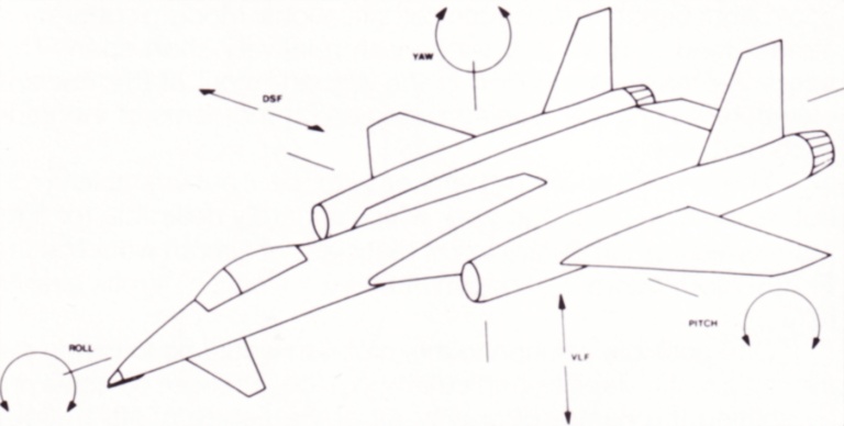
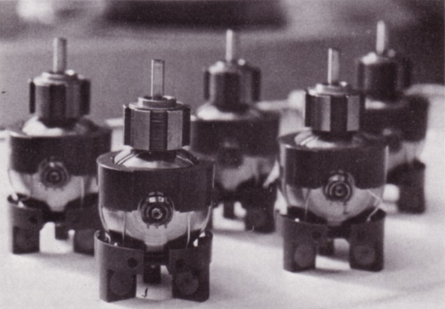
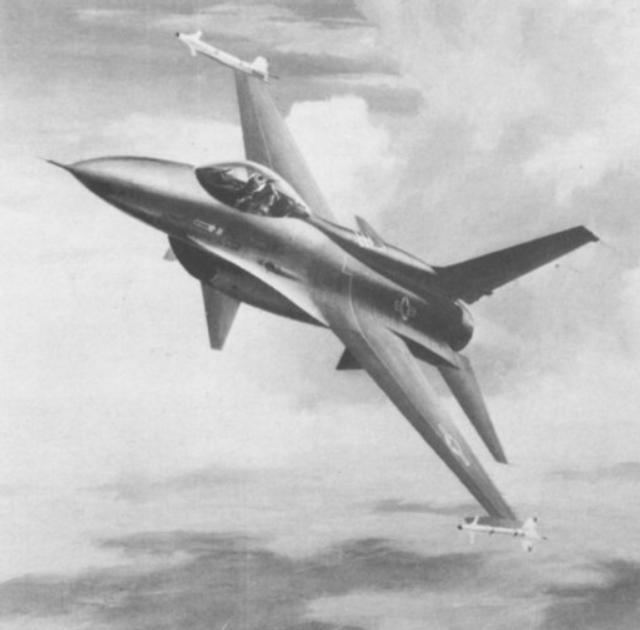
Aircraft, such as the F-14, satisfy 1.,2.,4. however they lag in 3. and definitely fail in 5.. The basic cause is that they employ conventional mechanical/hydraulic systems, which, in spite of their conceptual simplicity, become enormously complex in these instances. The only current system which satisfies 1. to 5. adequately is fly-by-wire control. Fly-by-wire Control Systems. As the name implies, fly-by-wire employs electrical signals to transmit information from the cockpit to the control actuators. Control elements, e.g. control stick, rudder pedals, are fitted with mechanical / electrical transducers - either force (F-16) or position sensing devices, which generate electrical signals corresponding to the given command. Here is where we must make the distinction between analogue and digital systems. Analogue systems operate with electrical analogues to real quantities. An example would be a device transmitting a quantity from 0 to 100% with an electrical voltage output of 0 to 10 Volts. A value of 15% would generate an output of 1.5 Volts. The number of ways in which analog information can be encoded is virtually unlimited. Information can be coded into voltage, frequency, phase or combinations of these, it can also be compressed prior to encoding, enabling more of it to be transmitted at once. Digital systems operate in binary. The binary number system (as compared to the decimal system we use) has only two values, 1 and 0. 2 forms a unit analogous to 10, 4 to 100, 8 to 1000, hence we can express a number such as six (6) as 110. 1,2,3... corresponds to 1, 10, 11.... Any number can be converted into binary, a digital device can then generate an output with only two states, on and off, corresponding to 1 and 0. All digital computers employ binary. Analog and digital systems both have advantages and disadvantages. Analog systems are, generally, simpler and less demanding in component parameters, such as speed. On the other hand, they are more susceptible to induced noise and interference, as the information content is carried within fine variations of some signal parameter. A digital system need only discriminate between on and off, the information being carried by sequences of binary numbers. Digital systems may be easily reconfigured by changes in software, whereas an analog system, hardwired, would require rebuilding. When analog systems fail, they often merely degrade in performance, a failure of a similar type could completely disable a digital device. The signals generated by the control elements are then used to control the control surface actuators. However, the raw output of a cockpit control element is hardly enough for that. It is modified by a stability augmentation computer. The computer compares the aircraft's actual motion, as sensed by gyros and accelerometers, and corrects it to a control law, improving the aircraft's handling. This type of system is used by the Tornado GR.1/F.2, which employs triplex control output sensing and computing, and quadruple electric control of the hydraulic control surface actuators. Further safety is provided by a mechanical backup for pitch/roll control. A similar approach was used in the YC-15 AMST STOL transport, which uses blown flaps to enhance short field performance. Variations in engine thrust can cause additional moments in roll and pitch, which would complicate the handling of such an aircraft. Aircraft configured for direct force control featuring variable incidence wings, beavertail elevator and control surfaces beneath nose. DSF - direct side force, VLF - vectored lift force. (Carlo Kopp) These tiny robot-like units are actually intricate components - subminiature gyroscopes used to guide aircraft, ships, missiles and torpedoes. The finished GR-G5 rate gyros, built by Northrop, are only two inches long and weigh less than five ounces. The GR-G5 is the most widely used rate gyroscope in the world, and is used in a quadruple-redundant system in the F-16 fly-by-wire flight control system. (Northrop) In either instance the fly-by-wire system, aside from improving reliability and its associated factors, is used to modify the response of the aircraft. This is, by no means, full utilization of the potential offered by electronic flight control. Artificial Stability and the Control Configured Vehicle. As is very often the case, the primary role of an aircraft carries the most weight in determining its aerodynamic configuration. With requirements for performance mounting and funds available dwindling, the option of variable geometry has become less attractive in the seventies and eighties - thus hardly leaving means to optimize an aircraft's performance throughout its whole operating range. With special applications as the Space Shuttle this becomes even more of a problem. One possible way of eliminating this problem is the use of artificial stability. A conventional aircraft, with a large degree of natural stability, can be represented, generally, as a system comprised of three basic elements - the pilot, the controls, the vehicle itself. Their interaction determines the function of the system. The path of this interaction is evident from the diagram - the pilot inputs commands via the controls; the vehicle, in turn, responds. The pilot then receives information, by visual cues from the attitude sensors (e.g. artificial horizon) and/or the external world, as to the exact nature of the response, enabling him to correct. Thus the pilot and aircraft are engaged in a feedback loop, the pilot guiding the aircraft through its mission and also correcting unwanted deviations generated by the natural behaviour of the aircraft. Here is where the factor of stability becomes apparent. Stability can be broadly defined as a system's ability to return to its initial state after receiving some stimulus. In aircraft we define static and dynamic stability. Static stability can be described as a measure of an aircraft's ability to return to its level attitude, following some change in attitude. In a statically stable aircraft, a change in attitude generates restoring forces, which oppose the change. This leads us to the concept of dynamic stability. The restoring forces in the statically stable aircraft act as long as its attitude differs from level, thus imparting an acceleration in the sense opposed to the change. This acceleration will cause the aircraft to swing back and overshoot, generating in turn another set of restoring forces, with identical effects. The aircraft will swing back and forth, if it's dynamically stable the overshoot will get smaller and smaller till it dies off, if it's unstable the overshoot will get greater with every cycle, throwing the aircraft out of control. The handling qualities of an aircraft are given by its stability. Too much stability results in a sluggish, unresponsive machine, with large control forces, on the other hand too little is characterized by overresponsive, sensitive controls. The lower the natural static stability of the aircraft, the larger the number of corrections required, thus diverting attention from other tasks. This doesn't last forever, because there comes a point where the pilot himself can no longer respond fast enough to make the appropriate correction, with that degree of instability the aircraft becomes unflyable. A large number of current applications point to the necessity of lower static stability, for one reason or another, yet the aircraft must remain flyable. In a Control Configured Vehicle (diagram 2.) corrections to the aircraft's attitude are carried out by a computer. Assuming the pilot is not touching the controls, we shall examine the system's behaviour. The aircraft, being statically unstable, deflects from its level attitude (e.g., the effect of a short gust). Little or no restoring forces are generated to impede the process. When this occurs, the attitude rate sensors detect the motion and generate a corresponding signal. This signal is received by the flight control computer (FCC), which compares it with the output signal generated by the cockpit controls. In this instance, the FCC recognizes the output for level flight and actuates the corresponding control surfaces to correct. In the manner the FCC, vehicle and rate sensors are locked into a feedback loop - the FCC and rate sensors generating the whole system's stability - hence the term artificial stability. The implications of this type of structure are enormous, as it allows unparalleled flexibility. The manner in which the aircraft responds to control inputs can be simply programmed into the computer, thus enabling us to exactly create the type of response and handling we require. The same feedback loop correction effect applies to all control input implied manoeuvers, hence you get a response configured by the aircraft's control system. Thus the term Control Configured Vehicle. Implementation. Fly-by-wire is the natural choice for systems employing artificial stability, as it uses very much the same structure. The FCC is the primary element in the system. As a rule it is redundant, employing three, four or five identical computers, all operating simultaneously and all under the supervision of a built in self test which isolates a malfunctioning unit. Earlier CCVs (eg, GD F-16) employ analogue systems, capitalizing on simplicity and reliability, however, digital systems are on the way, offering the possibility of reprogramming the system's response to suit a given requirement. Digital computers are easier to interface with other computers, so that structures built up of several systems may be linked, enabling fully automatic delivery modes or TFR (including appropriate radar mode) functions to be implemented. The second critical element in the control system is the attitude sensing unit. The ubiquitous gyroscope fills this function - a gyro is employed to sense changes in attitude about each of the aircraft's three axes. Again, redundancy is used for reliability. General Dynamics AFTI F-16 conversion features both Control Configured Vehicle fins in addition to fly-by-wire control systems. (General Dynamics). Pitch, roll and yaw gyros are usually combined in a unit, the number. of units used depends on the degree of redundancy (triplex, quadruplex). For instance, the F-16 employs a quadruply redundant system with four Line Replaceable Units (LRUs), each LRU containing three Northrop GR-G5 rate gyros, measuring pitch, roll and yaw respectively. Control signals within the aircraft are distributed by electrical cables, again multiply redundant, the signals are analogue or digital. A point worth noting is the opportunity to route control signal carrying lines through differing paths within the airframe, lowering the probability of a control actuator being isolated by combat damage. Though cables may suffice for the distribution of analog signals, they do have limitations which become apparent with digital systems, as their limited bandwidth affects the transmission of high data rate signals. The solution to the problem are optical fibres. Optical fibres are made of high grade silica glass, the fibre itself has two layers, a core with a higher refractive index and a surface layer with a lower index. Light incident on the flat ends of fibres can propagate with very low losses and with little distortion, enabling the transmission of high data rate signals over relatively large distances. The low weight, compactness (diameter a fraction of a millimetre), high transmission rate and immunity to electromagnetic interference (a factor to be considered in aircraft with major parts of their structures made of composites - these materials do not offer the automatic electromagnetic screening of aluminium or other metal) make optic fibres very close to ideal for aviation purposes. Artificial Stability and the Fighter. One of the most basic requirements for a fighter aircraft is manoeuverability. Prior to the age of supersonic aircraft, the problem of finding the optimal amount of stability was fairly straightforward, however the necessary aerodynamics for supersonic flight began to introduce complications. Modern supersonic aircraft tend to have thin wings with relatively short span. This alters the mass distribution in the aircraft, most of the mass is distributed along the fuselage, increasing moments of inertia in pitch and yaw. The result is an aircraft very easy to roll, if not unstable in roll, but reluctant in pitch and yaw, which is hardly desirable for tight manoeuvering. An illustration of that class of aircraft would be the F-105 Thud, quote "...it doesn't turn very well.... it rolls beautifully ...". One possible solution to this problem would be lowering the aircraft's static stability, particularly in pitch. This can be achieved by shifting the centre of gravity aft of the centre of lift, thereby creating a nose-up pitching moment, which will assist in rotating the aircraft's nose into a tight turn. However, the resulting loss in stability must be countered and this is the task of artificial stability. Both the GD F-16 and the Mirage 2000 employ this means of improving manoeuverability, Rockwell's HiMAT technology demonstrator also uses artificial stability. By far, though, the most important contribution which artificial stability can offer to the fighter is the use of direct force control modes. Conventional aircraft control modes are indirect, the aircraft must be pointed in a direction by means of its pitch/roll/yaw controls. The controls serve to change the aircraft's attitude, the change in attitude changes the direction of the resultant force vector acting on the aircraft and the flightpath is altered. Thus translation must be generated through rotation, indirectly. In direct force control modes the control forces act directly on the aircraft, generating the desired translation. By creating balanced couples of forces a constant attitude may be maintained in translation, enabling "pointing" without its indirect control effects. The implications for gunnery and ground attack are obvious. The implementation of direct force control does require changes in aerodynamics. GD's F-16CCV/AFTI-16 project uses an F-16 with canards mounted on either side of the air intake. A configuration under study by McDonnell Douglas involves the use of variable incidence wings, a beavertail elevator and vertical control surface under the nose. In either case it would be beyond the ability of any pilot to fly the aircraft without some stability augmentation to cancel out the secondary control effects and the indirect control effects, both which would seriously affect handling in direct force modes. The advantages offered by a CCV configuration are obvious. Control laws for direct/indirect/combined control modes can be stored in the computer (FCC) and invoked at will by the pilot by merely hitting the appropriate button, thus enabling instant transitions between modes. In a dogfight, the pilot could simply apply vectored lift to dislodge an opponent on his tail, by translating upwards and slowing, the opponent then overshoots and finds himself with his prey behind and above him. The use of direct sideforce control to point the aircraft while tracking a target avoids the necessity to correct in more than the axis necessary. Vectored lift is also energetically more favourable than the use of in-flight thrust reversal, as not all the kinetic energy is lost in an "overshoot" type situation. Another factor to be considered is the interfacing of the aircraft with a mission or fire control computer. Ultimately this offers the possibility of preprogrammed manoeuvers, such as particular evasive action or delivery modes, thus seriously interfering with the enemy's manual tracking or first/second order tracking computers. It's difficult to predict, at this point, what path
development will take, but the CCV is a concept with wide applications
and there is definitely potential for a lot of future development. |
|||
|
|||||||||||||
|
|
|
|
|
|
|
|
||||||
|
|
|
|
|
|
|
|
||||||
|
|||||||||||||
| Artwork, graphic design, layout and text © 2004 - 2014 Carlo Kopp; Text © 2004 - 2014 Peter Goon; All rights reserved. Recommended browsers. Contact webmaster. Site navigation hints. Current hot topics. | |||||||||||||
|
Site Update
Status:
$Revision: 1.753 $
Site History: Notices
and
Updates / NLA Pandora Archive
|
|||||||||||||
|
|
Tweet | Follow @APA_Updates | |||||||||||
|
|
|||||||||||||
|
|
|||||||||||||