Assessing
Joint Strike Fighter
Defence Penetration Capabilities
Annex A, B, C
|
Air
Power Australia Analysis
2009-01
7th January 2009
|
by Dr Carlo Kopp, SMAIAA, MIEEE, PEng
|
©
2008, 2009 Carlo Kopp
|
|
- Annex A Threat Operating
Bands
- Annex B Engagement Envelopes
-
Representative Threats
- Annex C Joint Strike Fighter
Lower Fuselage and Nozzle RCS
Modelling
|
|
Annex A Threat
Operating Bands
|
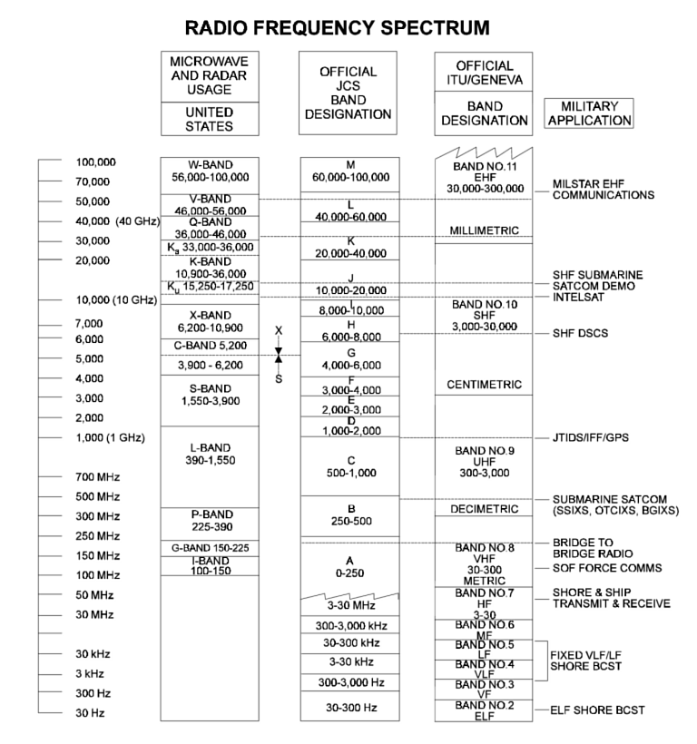
US
DoD
Band
Allocation
Chart
|
Radar
Type
|
NATO
Designation
|
RF
Band
|
SAM
System
|
NATO
Designation |
Role/Function
|
Status
|
P-18
|
Spoon
Rest
D
|
VHF
|
S-75,
S-125
|
SA-2,
SA-3
|
Acquisition
|
Legacy/Upgrade
|
1L13
Nebo
SV
|
-
|
VHF
|
S-300PMU/S-400 |
SA-20,
SA-21
|
Acquisition |
Production
|
1L119
Nebo
SVU
|
-
|
VHF
|
S-300PMU/S-400
|
SA-20,
SA-21 |
Acquisition |
LRIP
|
| 5N84AE
Oborona-14 |
Tall
King
|
VHF
|
S-75,
S-125,
S-200
|
SA-2,
SA-3,
SA-5
|
Acquisition |
Legacy/Upgrade
|
5Zh66
Nebo
UE
|
Tall
Rack
|
VHF
|
S-400
|
SA-21
|
Acquisition |
Production
|
P-15/15M/19
|
Flat
Face
/
Squat
Eye
|
UHF
|
S-75,
S-125
|
SA-2,
SA-3
|
Acquisition |
Legacy/Upgrade
|
| 51U6
Kasta
2E1/2E2
|
-
|
UHF
|
S-75,
S-125
|
SA-2,
SA-3 |
Acquisition |
Production
|
| 67N6E
Gamma
DE
|
-
|
L
|
S-300PMU/S-400
|
SA-20,
SA-21
|
Acquisition |
Production
|
| 59N6E
Protivnik-GE |
-
|
L
|
GCI
|
-
|
Acquisition |
|
P-35M/37
/1L117
|
Bar
Lock |
S
|
GCI
|
-
|
Acquisition |
Legacy/Upgrade |
| 96L6E
|
Cheese
Board
|
S
|
S-300PMU/S-400
|
SA-20,
SA-21 |
Acquisition |
Production
|
| 5N66M/76N6 |
Clam
Shell |
|
- |
SA-10,
SA-20
|
Acquisition |
Production |
| 36D6/ST-68M |
Tin
Shield |
S |
S-300PT/PS/PMU |
SA-10,
SA-20 |
Acquisition |
Legacy/Upgrade |
| 64N6E/E2 |
Big
Bird
|
S
|
S-300PMU1/PMU2 |
SA-20 |
Acquisition |
Production |
92N6E
|
Big
Bird |
Big
Bird |
S-400 |
SA-21 |
Acquisition |
Development
|
| P-35M/37
|
Bar
Lock
|
S
|
S-75,
S-125
|
SA-2,
SA-3 |
Acquisition |
Legacy/Upgrade
|
| TRS-2100
Tiger
S
|
-
|
S
|
-
|
|
Acquisition |
Production
|
9S15M
Obzor-3
|
Bill
Board |
S |
S-300V/VM |
SA-12/23
|
Acquisition |
Production |
| 9S18
Kupol |
Tube
Arm |
S |
9K37M
Buk |
SA-11 |
Acquisition |
Legacy/Upgrade |
| 9S18M1
Kupol-M |
Snow
Drift |
S |
9K37M1
Buk-M1 |
SA-17 |
Acquisition |
Production |
| 1RL-144
Tunguska
M |
Hot
Shot |
S |
9M311 |
SA-19 |
Acquisition |
Production |
1RL-144M
Pantsir
S1
|
Hot
Shot |
S |
9M335
/
57E6 |
SA-22 |
Acquisition |
Production |
| SNR-75 |
Fan
Song
|
S/X
|
S-75 |
SA-2 |
Engagement |
Legacy/Upgrade |
| 1S91 |
Straight
Flush |
S/X |
ZRK
Kub
|
SA-6 |
Acquisition |
Legacy/Upgrade |
| 4R33
Baza |
Land
Roll |
S/X |
9A33BM3
ZRK
Romb
|
SA-8 |
Acquisition |
Legacy/Upgrade |
| 1S91 |
Straight
Flush |
X
|
ZRK
Kub |
SA-6 |
Engagement |
Legacy/Upgrade |
| 5N62 |
Square
Pair
|
X
|
S-200
|
SA-5
|
Engagement |
Legacy |
9S19M2
Imbir
|
High
Screen
|
X
|
S-300V/VM |
SA-12/23 |
Acquisition/ABM |
Production |
30N6E
|
Flap
Lid
|
X |
S-300PT/PS/PM |
SA-10 |
Engagement |
Legacy/Upgrade |
| 30N6E1 |
Tomb
Stone
|
X |
S-300PMU1 |
SA-20 |
Engagement |
Legacy/Upgrade |
| 30N6E2 |
Tomb
Stone
|
X |
S-300PMU2 |
SA-20 |
Engagement |
Production |
92N2E
|
Grave
Stone
|
X |
S-400 |
SA-21 |
Engagement |
Production |
| 9S32 |
Grill
Pan |
X
|
S-300V/VM |
SA-12/23 |
Engagement |
Production |
| 9S35M1 |
Fire
Dome |
X
|
Buk-M1
9K37M1
|
SA-11/17
|
Engagement |
Production |
SNR-125
|
Low
Blow |
X
|
S-125
|
SA-3
|
Engagement |
Legacy/Upgrade |
| RPK-2
Tobol
|
Gun
Dish
|
X
|
ZSU-23-4P
|
ZSU-23/4P
|
Engagement |
Legacy/Upgrade
|
| Tor/Tor
M1/M2 |
Scrum
Half |
X |
9A331M |
SA-15A/B/C |
Acquisition |
Production |
| 4R33
Baza |
Land
Roll |
X/Ku |
9A33BM3
ZRK
Romb
|
SA-8 |
Engagement |
Legacy/Upgrade |
| Tor/Tor
M1/M2
|
Scrum
Half
|
K
|
9A331M
|
SA-15A/B/C
|
Engagement |
Production
|
| 1RL-144
Tunguska
M
|
Hot
Shot
|
Ka
|
9M311
|
SA-19
|
Engagement
|
Production
|
| 1RL-144M
Pantsir
S1
|
Hot
Shot
|
Ka
|
9M335
/
57E6
|
SA-22
|
Engagement
|
Production
|
Spectral
Range
-
Electronic
Threat
Environment 2008
|
System
|
VHF
|
UHF
|
L
|
S
|
S/X
|
X
|
X/Ku
|
K
|
Ka
|
|
Surveillance
/
Target
Acquisition
|
|
|
|
|
|
|
|
|
Engagement
/
Fire
Control
|
SA-2+
Guideline
|
Spoon
Rest
|
Kasta
2E1/2E2 |
|
|
Fan
Song |
|
|
|
|
SA-3+
Goa
|
Spoon
Rest |
Kasta
2E1/2E2 |
|
|
|
Low
Blow |
|
|
|
SA-5+
Gammon
|
Tall
King |
|
Cheese
Board,
67N6E,
59N6E |
Bar
Lock,
Tin
Shield |
|
Square
Pair,
Flap
Lid |
|
|
|
SA-6+
Gainful
|
Spoon
Rest |
Kasta
2E1/2E2 |
67N6E,
96L6E,
59N6E |
Bar
Lock,
Tin
Shield |
Straight
Flush |
Straight
Flush |
|
|
|
SA-8A/B+
Gecko
|
Nebo
SV
|
Kasta
2E1/2E2 |
|
|
Land
Roll |
|
Land
Roll |
|
|
SA-10A+
Grumble
|
Tall
King |
|
|
Tin
Shield,
Clam Shell
|
|
Flap
Lid
|
|
|
|
| SA-10B+
Grumble |
Tall
King |
|
|
Tin
Shield,
Clam Shell |
|
Flap
Lid |
|
|
|
| SA-10C+
Grumble |
Nebo
SVU |
|
67N6E,
96L6E,
59N6E |
Tin
Shield,
Clam Shell |
|
Flap
Lid |
|
|
|
SA-11+
Gadfly
|
Nebo
SV
|
Kasta
2E1/2E2 |
|
Tube
Arm,
Snow
Drift |
|
|
|
|
|
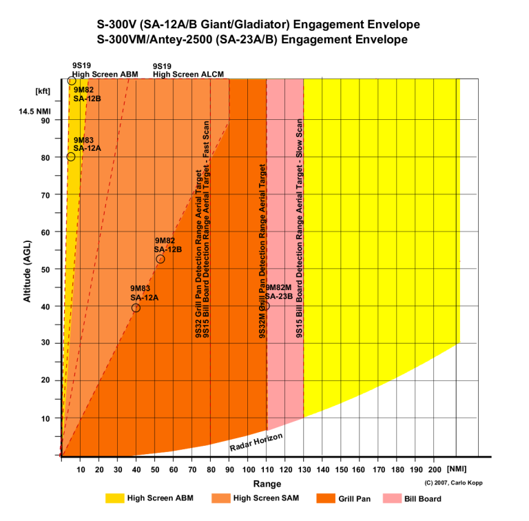
SA-12
Gladiator/Giant
|
Nebo
SV
|
|
|
Bill
Board
|
|
Grill
Pan,
High
Screen
|
|
|
|
SA-15
Gauntlet
|
Nebo
SV
|
Kasta
2E1/2E2 |
|
|
|
Scrum
Half
|
|
Scrum
Half
|
|
SA-17
Grizzly
|
Nebo
SV
|
Kasta
2E1/2E2 |
|
Snow
Drift
|
|
Fire
Dome
|
|
|
|
SA-19
Grison
|
Nebo
SV
|
Kasta
2E1/2E2 |
|
Hot
Shot
|
|
|
|
|
Hot
Shot
|
SA-20A
Gargoyle
|
Nebo
SVU
|
|
Cheese
Board |
Big
Bird,
Clam Shell
|
|
Tomb
Stone
|
|
|
|
| SA-20B
Gargoyle |
Nebo
SVU
|
|
Cheese
Board |
Big
Bird,
Clam Shell
|
|
Tomb
Stone
|
|
|
|
SA-21
|
Nebo
UE,
Nebo SVU |
|
Cheese
Board |
Big
Bird
|
|
Grave
Stone
|
|
|
|
SA-22
Greyhound
|
Nebo
SV |
Kasta
2E1/2E2 |
|
Hot
Shot |
|
|
|
|
Hot
Shot |
| SA-23
Gladiator/Giant
|
Nebo
SVU
|
|
|
Bill
Board
|
|
Grill
Pan,
High Screen |
|
|
|
|
|
|
|
|
|
|
|
|
|
|
|
|
|
|
|
|
|
|
|
|
|
|
|
|
|
|
|
|
|
+ Plus denotes legacy systems supported by new
technology radars
|
| Spectral
Range - Electronic
Threat Environment 2008 |
|
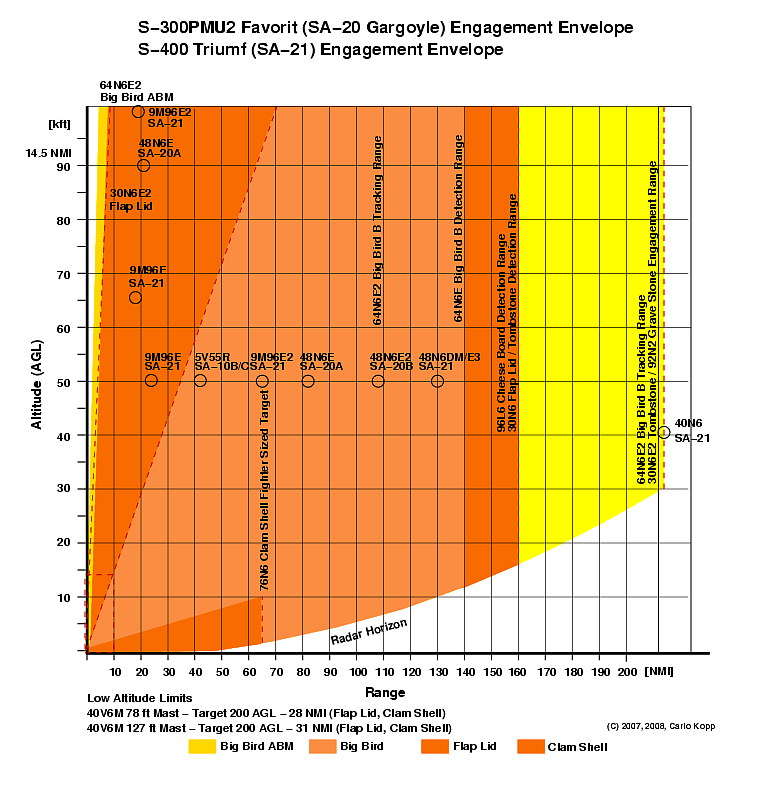
Annex B Engagement Envelopes -
Representative Threats
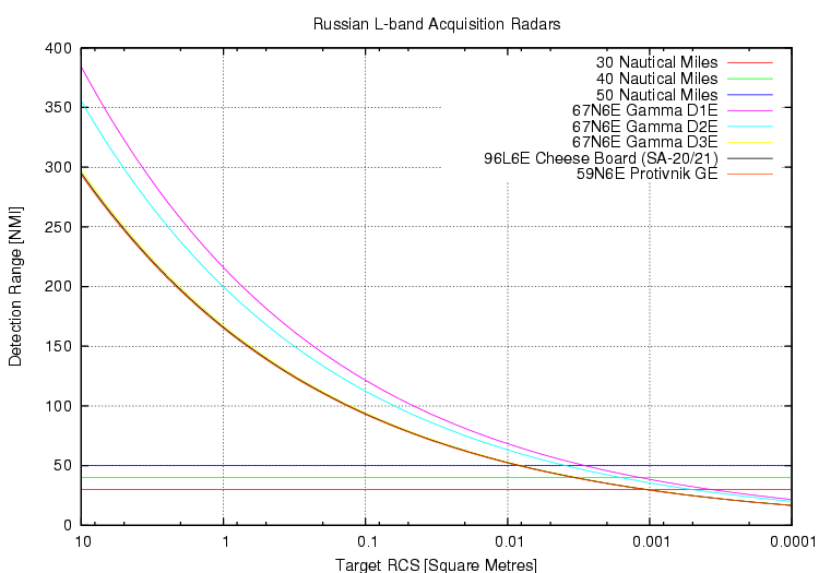
Since 1991 most new Russian radar designs
have been in the L-band and VHF-band, with the Cold War era UHF band
designs re-engineered and digitised. Significantly the L-band designs
are capable of tracking -20 dBSM RCS targets in the 50 - 70 NMI range
window, and -30 dBSM targets in the 40 - 50 NMI range window. The
"shoot and scoot" LEMZ 96L6E Cheese Board is used in the SA-21 system
and is an option for the SA-20 system. The 67N6E and 59N6E are
available as options for the SA-21 system. Performance curves based on
Russian datasheets.
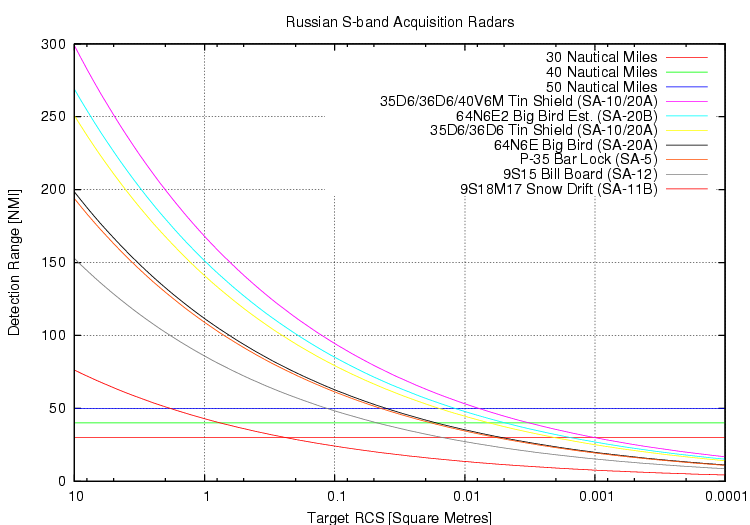
Russian S-band acquisition radars used
with SAM systems. While these are mostly legacy Cold War designs, some
remain in production at this time. The 36D6/ST-68U/UM Tin Shield family
of radars remains widely used and variants are deployed with SA-10 and
SA-20 SAM batteries for long range acquisition. Estimated performance
for the SA-20B 64N6E2 Big Bird is based on increased 48N6E2 missile
range compared to the 48N6 used with the 64N6/64N6E, a shorter
detection range would not be compatible with the weapon. Performance curves based on Russian
datasheets.
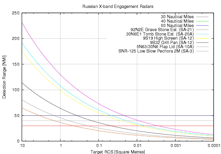
Most Russian SAM engagement radars operate
in the X-band. There is a clear disparity between power aperture
requirements for the medium range SAM systems (SA-3, SA-10A, SA-12) and
the newer long range SAM systems (SA-20, SA-21). Estimated performance for the SA-21 92N2E
Grave Stone and SA-20 30N6E1 Tomb Stone is based on increased
48N6E1/2/3 missile range compared to
the 5V55K used with the 30N6, a shorter detection range would not
be compatible with the weapon.
Performance curves based on Russian datasheets.

VHF band radars present a major risk for
fighter sized VLO and LO aircraft, as virtually all airframe
shaping becomes ineffective or at best partly effective in this band,
in addition to problems arising with absorbent material skin depth at
~100 MHz. Numerous Russian source cite an RCS in the VHF band for
the F-117A Nighthawk at 0.5 m2, a figure which would
be similar for the Joint Strike Fighter. Recent designs such as the Nebo SVU
include solid state AESA technology and provide comparable angle and
range accuracy to S-band acquisition radars. Performance curves based
on Russian datasheets.
Provisional
data
-
Russian
sources.
Provisional
data
-
Russian
sources
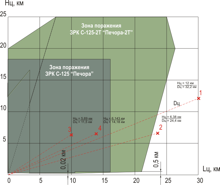
S-125
/ SA-3 and S-125-2T Pechora 2T block upgrade firing trial results. The
Pechora 2T is a characteristic of contemporary digital block upgrades
to widely used Soviet era SAMs. The improved autopilot algorithm
significantly extends the engagement envelope of the weapon system. The
best range achieved was 16 NMI. Provisional data - Tetraedr JSC.
|
Annex C Joint
Strike Fighter Lower Fuselage and Nozzle RCS
Modelling
The Radar Cross Section (RCS)
performance of the lower fuselage section and nozzle was assessed at
three
important frequencies of interest 1 GHz (L-band), 4 GHz (S-band) and 10
GHz (X-band), as these present the most likely bands in which a range
of legacy and contemporary acquisition and engagement radars operate.
Refer Annex A.
Modelling was performed using the POFacets 3.1 simulator which produces
optimistic results as the simulator does not include edge diffraction
effects and surface traveling wave effects. The actual and measurable
Radar Cross Section would be higher due to impact of shaping features
excluded in the model, and the contributions not predicted by the
simulator. A calibration
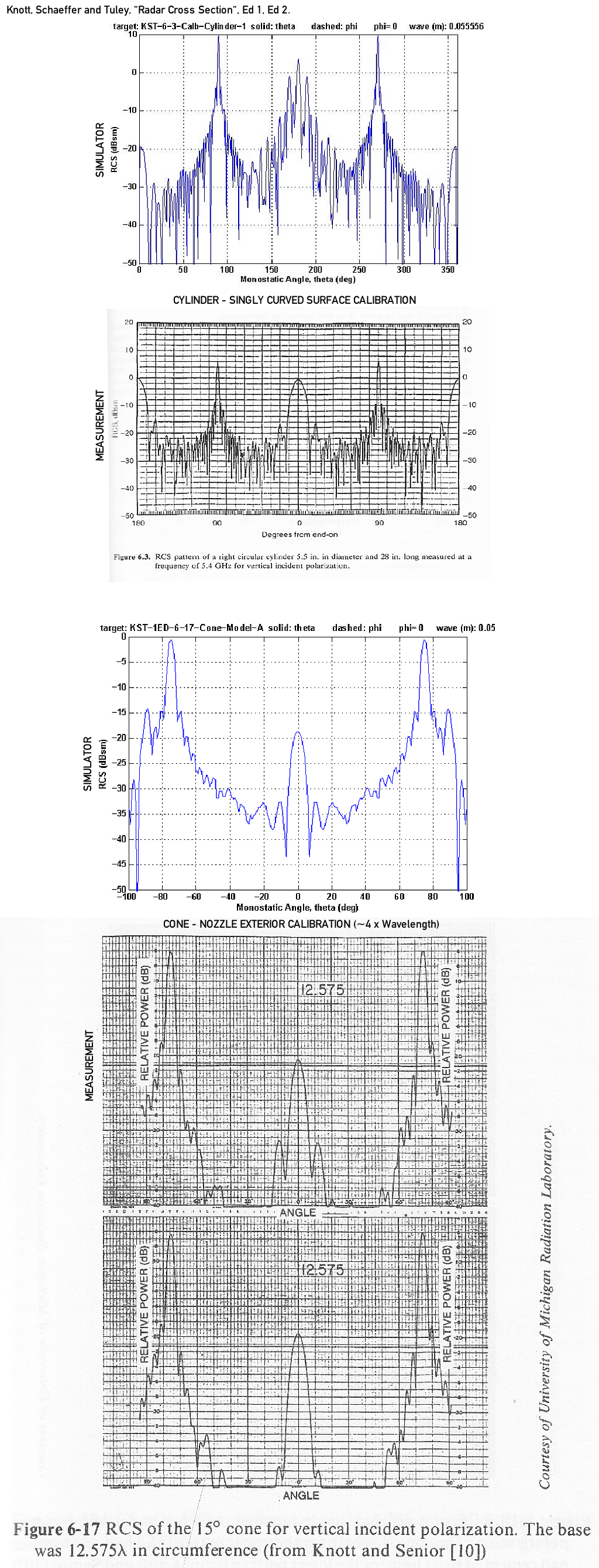
check was performed to validate simulator results against published
test data, using Fig 6-3 at
5.8 GHz, and Fig 6-17 at 6 GHz from Knott, Schaeffer and Tuley, 2nd and
1st Editions respectively. The simulator
yielded close agreement with measurement. Other shapes specifically
applicable to this problem were also modelled, with consistent
agreement against published measurements.
Because the simulator uses the physical optics model for computing the
target cross section, shapes must be subdivided into triangular facets.
The shape models designed and implemented for both the nozzle and lower
fuselage were constructed with fidelity in mind, the aim being to avoid
unwanted quantisation errors.
The strategy adopted in modelling was to look at a number of
operationally and tactically critical azimuth angles from which a
threat might illuminate the aircraft in the bands of interest, and
within each of these azimuth angles the simulation covers the full
range of elevations of interest. The 'traditional' and popular model in
which a polar plot of RCS is produced within the horizontal plane of
the aircraft might present nicely and be easy to interpret, but it is
not very useful if we need to consider real world threats which may
appear at a wide range of elevation angles relative to the aircraft in
flight.
The
diagram below shows the
cardinal depression angles for an aircraft at the tropopause,
accounting for the curvature of the earth and atmospheric refractive
effects which 'bend' the ray path between the aircraft and threat
radar. The specific angles in this diagram were determined using
Russian
specifications for missile kinematic range, the SBF
refractive
model for short ranges, and an exponential
CRPL
refractive
model
for ranges in excess of 100 nautical miles.
It is important to observe that in straight and level flight at medium
and high altitudes all
surface based threats are firmly in the lower hemisphere, putting a
premium on low Radar Cross Section in the angular range between 3.7°
and
36.5° , as area defence missile systems and associated acquisition
radars will illuminate the aircraft
within this angular range.
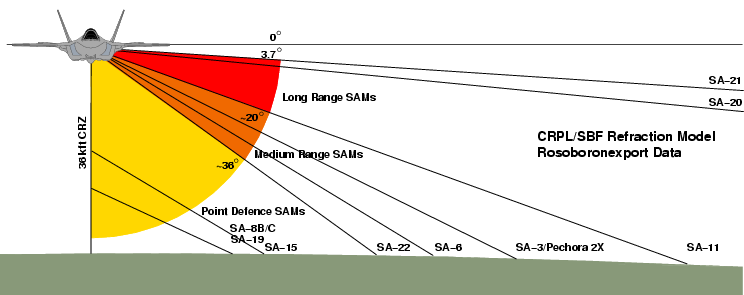
Threat depression angles as a
function of type and missile kinematic range.
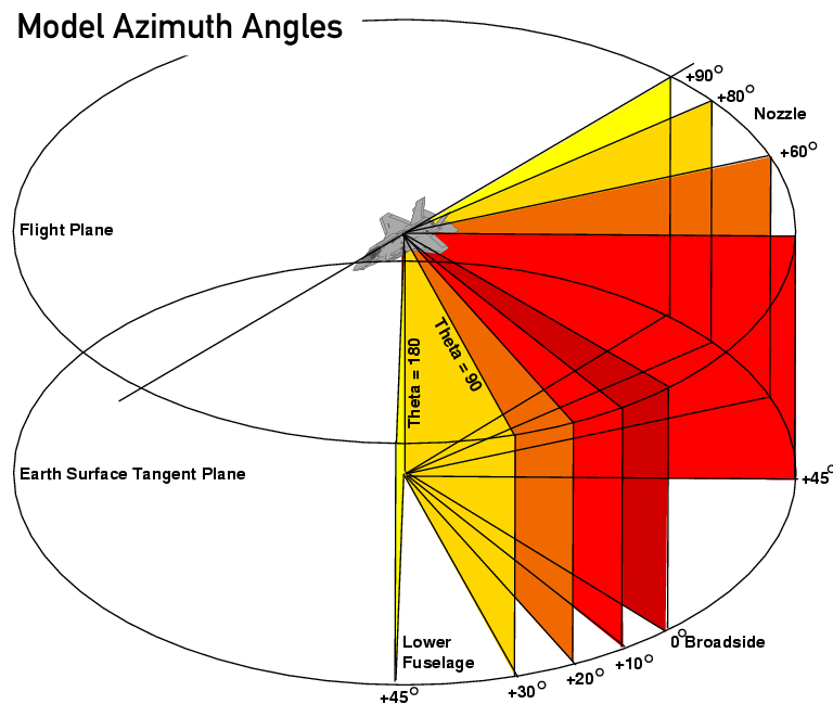
Equally so, careful
consideration was given to the choice of azimuth angles for modelling.
Lower Centre
Fuselage Model
The Joint Strike Fighter lower
centre fuselage area represents an area of major concern in the
aircraft’s overall radar cross section, as a result of a series of
design changes introduced during the SDD program.
These result primarily from the extension, downward, of the two
outboard main weapon bays, and the use of additional symmetrical
blended fairings on the lower fuselage, parallel and toward the aft and
centre of the weapon bays. Both of these design features destroy the
essentially flat lower fuselage geometry demonstrated in the X-35
prototypes.
Modelling was performed to
determine the order of magnitude Radar Cross Section contribution of
this part of the airframe shape, with a specific focus on
vulnerabilities arising to threats in the beam sectors of the Joint
Strike Fighter aircraft.The solid shape model for this portion of the
design is optimistic in its Radar Cross section prediction. This is
because it excludes the doubly curved surfaces at the front and aft
ends of the weapon bays and the fuselage fairings. The absolute and
relative dimensional accuracy of the fuselage section employed is
better than 3%, and original photographic imagery was employed to
generate this section.
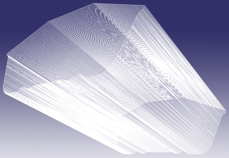
Wireframe rendering of the solid model for
JSF lower fuselage geometry employed for RCS modelling. This model
accurately represents the complex singly curved section of the lower
centre fuselage, but does not represent the longitudinal taper or the
problematic doubly curved shapes at the weapon bay and ventral blister
transitions. The model was produced by digitising a section from a
photograph and after scaling, extending the section into a solid using
a custom C language program (Author).
JSF Lower Fuselage RCS Model L-band @ 1.0
GHz - Peak/Average RCS [dBSM] in Angular Range V-pol
|
Depression
Angle / Angle Off Beam
|
10°
|
20°
|
30°
|
45° |
Long
Range
SAMs
[-3.6°
to -20°]
|
+9.0/0.0
|
+5.0/-8.0
|
+1.0/-13.0
|
-4.0/-12.0
|
| Medium
Range
SAMs
[-20°
to -36°] |
+6.0/-8.0
|
+5.0/-8.0
|
+1.0/-13.0
|
-7.0/-14.0
|
| Short
Range
SAMs
[-36°
to -60°] |
+7.0/-5.0
|
+6.0/-10.0
|
-1.0/-13.0
|
-3.0/-11.0
|
|
|
JSF Lower Fuselage RCS Model S-band @ 3.0
GHz - Peak/Average RCS [dBSM] in Angular Range V-pol
|
| Depression
Angle
/
Angle
Off Beam |
10° |
20° |
30° |
45° |
| Long
Range
SAMs
[-3.6°
to -20°] |
+2.5/-10.0
|
-2.0/-13.0
|
-2.0/-15.0
|
-5.0/-15.0
|
| Medium
Range
SAMs
[-20°
to -36°] |
+1.0/-8.0
|
-6.0/-15.0
|
-6.0/-20.0
|
-12.0/-20.0
|
| Short
Range
SAMs
[-36°
to -60°] |
+2.0/-8.0
|
-3.0/-10.0
|
-6.0/-13.0
|
-1.0/-13.0
|
|
|
JSF Lower Fuselage RCS Model X-band @ 8.0
GHz - Peak/Average RCS [dBSM] in Angular Range V-pol
|
| Depression
Angle
/
Angle
Off Beam |
10° |
20° |
30° |
45° |
| Long
Range
SAMs
[-3.6°
to -20°] |
-5.0/-18.0
|
+1.0/-20.0
|
-9.0/-25.0
|
-3.0/-25.0
|
| Medium
Range
SAMs
[-20°
to -36°] |
-2.0/-18.0
|
-9.0/-20.0
|
-15.0/-25.0
|
-15.0/-25.0 |
| Short
Range
SAMs
[-36°
to -60°] |
-2.0/-10.0
|
-4.0/-15.0
|
-8.0/-20.0
|
-2.0/-22.0
|
|
|
| JSF
Lower
Fuselage
RCS
Model Ku-band @ 16.0 GHz - Peak/Average
RCS [dBSM] in Angular Range V-pol |
| Depression
Angle
/
Angle
Off Beam |
10° |
20° |
30° |
45° |
| Long
Range
SAMs
[-3.6°
to -20°] |
-4.0/-20.0
|
-5.0/-25.0
|
-15.0/-30.0
|
-8.0/-32.0
|
| Medium
Range
SAMs
[-20°
to -36°] |
-6.0/-20.0
|
-12.0/-25.0
|
-15.0/-25.0
|
-22.0/-32.0
|
| Short
Range
SAMs
[-36°
to -60°] |
0.0/-10.0
|
-6.0/-15.0
|
-7.0/-22.0
|
-2.0/-25.0
|
|
|
Colour
Coding
(Average
RCS
Only)
|
Safe
(<-30
dBSM)
|
Borderline
(>-30
dBSM)
|
Vulnerable
(>-20
dBSM) |
|
Notes:
|
- The table shows simulated RCS
contributions
by the lower centre fuselage section only in the beam/side aspect zone
for four representative bands. The actual RCS at these aspect angles
will be higher due to the contributions of the double curved surfaces
not included in the model, plus other airframe shaping features.
- Colour coding is based on average RCS
as this
magnitude guarantees a reliable track by a radar, and is very
conservative. In some instances the peaks are dense enough to permit
tracking.
- The -30 dBSM threshold for "safe" is
based on
the assumption that application of an absorbent coating or laminate
will reduce RCS by a further 10 dB or more thus driving the RCS
contribution of the lower fuselage into the VLO or "genuine stealth"
category.
|
|
Lower Centre
Fuselage Analysis
The results of modelling the
RCS
performance of the lower centre fuselage are entirely consistent with
'rule of thumb'
RCS estimation techniques which predict very poor performance in bands
where the shaping features no longer produce good effect. This is
evident in the results for the L-band and S-band, with performance
generally improving in the X-band, and best performance achieved in the
Ku-band.
Angular dependencies are interesting. In terms of depression
angles the best performance was achieved generally for distant threats,
as the distance is reduced RCS grows strongly due to the steeper
depression angles and increasing exposure of the contoured lower
fuselage to impinging illumination. The fuselage slab sides and chines,
copied from the F-22 design, are the principal reason for good upper
band performance at shallow depression angles.
In terms of azimuths, best performance was generally
achieved for threats in the forward quarter of the aircraft, with the
RCS contribution of the lower centre fuselage consistent with public
claims of -30 dBSM RCS performance in the X-band. That the simulation
yields such consistency with publicly disclosed RCS performance data
demonstrates that it performed accurately.
The most problematic aspects for the lower centre fuselage are those
where the contoured lower surface is exposed, especially if the azimuth
of illumination is close to the broadside beam aspect of the aircraft.
This is especially prominent for angles of ±10° to ±20°
off the beam, where average RCS values of up to 0 dBSM are observed in
the lower bands.
In conclusion, of the 48 angular sectors assessed in four bands, only
three yielded safe RCS performance, with 58 percent of these
angular/frequency extents yielding poor or very poor results.
At 1 GHz where newer Russian acquisition
radars such as the 96L6 Cheese Board (SA-21 and optional for SA-20) the
JSF is in difficulty even at its best performing beam sector lower
hemisphere aspects. Peak RCS exceeds a square metre and the skin depth
will present problems for absorbent coatings and laminates.
The JSF was optimised to perform best in
the X-band (above) and Ku-band, the intent being to frustrate
engagement radars associated with mobile battlefield point defence
weapons. While its lower hemisphere signature is better in these bands
relative to the L-band and S-band, medium and long range SAM engagement
radars waiting in ambush and engaging from shorter ranges will be able
to detect dense peaks produced by the contoured lower fuselage. Turning
away from the threat will significantly increase the observable RCS -
the bank angle adds to the depression angle relative to the threat
(below).
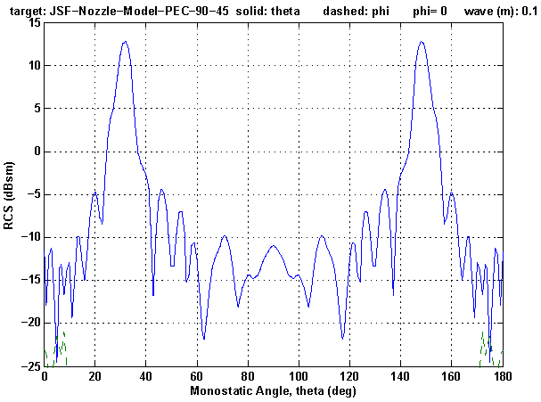
Axisymmetric
Nozzle Model
The Joint Strike Fighter
axisymmetric exhaust nozzle represents an area of major concern in the
aircraft’s overall radar cross section, and arises due to the use of
this specific class of nozzle geometry in preference to the slit
geometry models employed in all other US stealth designs.
The nozzle and aft fuselage interface designs employ three distinct
shaping features to reduce external shaping Radar Cross Section. These
are a serrated trailing edge, a serrated fuselage fairing, and very low
curvature nozzle petals.
The model employed assumes the internal tailpipe cavity is a perfect
absorber and makes no significant contribution to the performance of
the nozzle, ie the model represents specular returns from the outer
surface of the petals and nozzle aperture rim.
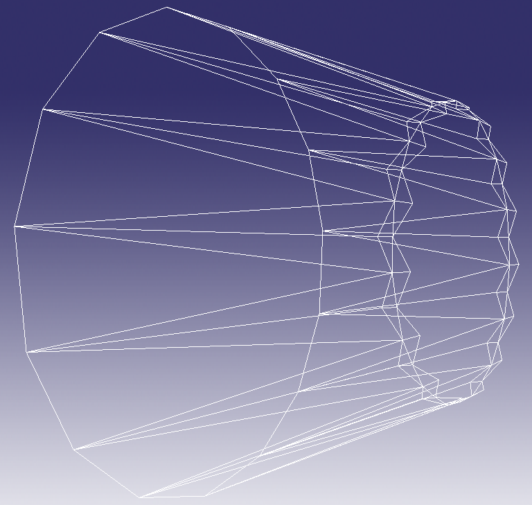
Wireframe rendering of the solid model for
JSF nozzle geometry employed for RCS modelling. This model
accurately represents the complex nozzle shape, but does not represent
the
problematic singly curved surface of the petal exterior. The model was
produced using
a custom C language program with cardinal dimensions scaled from
photographs and public US DoD line drawings (Author).
JSF Axisymmetric Nozzle RCS Model L-band @
1.0
GHz - Peak/Average RCS [dBSM] in Angular Range V-pol
|
Depression
Angle / Angle Off Beam
|
45°
|
60°
|
80°
|
90°
(Tail)
|
Long
Range
SAMs
[-3.6°
to -20°]
|
-13.0/-17.0
|
-8.0/-13.0
|
-8.0/-15.0
|
-4.0/-15.0
|
| Medium
Range
SAMs
[-20°
to -36°] |
-4.0/-7.0
|
-8.0/-13.0 |
-11.0/-16.0
|
-12.0/-17.0
|
| Short
Range
SAMs
[-36°
to -60°] |
+8.0/-2.0
|
+5.0/-8.0
|
-2.0/-12.0
|
-5.0/-12.0
|
|
|
JSF Axisymmetric Nozzle RCS Model S-band @ 3.0
GHz - Peak/Average RCS [dBSM] in Angular Range V-pol
|
| Depression
Angle
/
Angle
Off Beam |
45° |
60° |
80° |
90°
(Tail) |
| Long
Range
SAMs
[-3.6°
to -20°] |
-10.0/-14.0
|
-13.0/-17.0
|
-12.0/-17.0
|
+1.0/-17.0
|
| Medium
Range
SAMs
[-20°
to -36°] |
-7.0/-14.0
|
-12.0/-17.0 |
-13.0/-17.0
|
-17.0/-22.0
|
| Short
Range
SAMs
[-36°
to -60°] |
+13.0/-3.0
|
0.0/-12.0
|
-8.0/-18.0
|
-6.0/-18.0
|
|
|
JSF Axisymmetric Nozzle RCS Model X-band @ 8.0
GHz - Peak/Average RCS [dBSM] in Angular Range V-pol
|
| Depression
Angle
/
Angle
Off Beam |
45° |
60° |
80° |
90°
(Tail) |
| Long
Range
SAMs
[-3.6°
to -20°] |
-12.0/-17.0
|
-12.0/-22.0
|
-15.0/-22.0
|
+1.0/-22.0
|
| Medium
Range
SAMs
[-20°
to -36°] |
-7.0/-17.0
|
-13.0/-22.0 |
-12.0/-22.0
|
-20.0/-25.0
|
| Short
Range
SAMs
[-36°
to -60°] |
+12.0/-6.0
|
0.0/-12.0
|
-12.0/-18.0
|
-15.0/-18.0
|
|
|
| JSF
Axisymmetric Nozzle
RCS Model Ku-band @ 16.0 GHz - Peak/Average
RCS [dBSM] in Angular Range V-pol |
| Depression
Angle
/
Angle
Off Beam |
45° |
60° |
80° |
90°
(Tail) |
| Long
Range
SAMs
[-3.6°
to -20°] |
-12.0/-17.0 |
-17.0/-25.0
|
-19.0/-25.0
|
+1.0/-30.0
|
| Medium
Range
SAMs
[-20°
to -36°] |
-9.0/-17.0
|
-12.0/-22.0
|
-13.0/-23.0
|
-17.0/-25.0
|
| Short
Range
SAMs
[-36°
to -60°] |
+14.0/-10.0
|
-5.0/-15.0
|
-6.0/-18.0
|
-10.0/-25.0
|
|
|
Colour
Coding
(Average
RCS
Only)
|
Safe
(<-30
dBSM)
|
Borderline
(>-30
dBSM)
|
Vulnerable
(>-20
dBSM) |
|
Notes:
|
- The table shows simulated RCS
contributions
by the axisymmetric nozzle
for four representative bands. The actual RCS at these aspect angles
will be higher due to the contributions of the double curved surfaces
not included in the model, backscatter from the tailpipe cavity, plus
other airframe shaping features.
- Colour coding is based on average RCS
as this
magnitude guarantees a reliable track by a radar, and is very
conservative. In some instances the peaks are dense enough to permit
tracking.
- The -30 dBSM threshold for "safe" is
based on
the assumption that application of an absorbent coating or laminate
will reduce RCS by a further 10 dB or more thus driving the RCS
contribution of the lower fuselage into the VLO or "genuine stealth"
category.
|
|
Axisymmetric
Nozzle Analysis
The results of modelling the
RCS performance of the nozzle are entirely consistent with 'rule of
thumb' RCS estimation techniques which predict very poor performance in
bands where the serrated trailing edge is no longer effective. This is
evident in the results for the L-band and S-band, with performance
generally improving in the X-band, and best performance achieved in the
Ku-band.
Angular dependencies are also of much interest. In terms of depression
angles the best performance was achieved generally for distant threats,
as the distance is reduced RCS grows strongly due to the steeper
depression angles. In terms of azimuths best performance was generally
achieved for threats directly aft of the aircraft, but with the caveat
that a narrow cone centred on the axis of the nozzle exhibits an RCS of
around 1 square metre for the upper three bands, which is also
consistent with 'rule of thumb' estimators for nozzles.
The most problematic aspects for the nozzle are those in close
proximity to the normal to the nozzle taper angle, which result in
large specular returns over an angular extent of up to 10°, observed in
all bands and with all azimuths.
In conclusion, of the 48 angular sectors assessed in four bands, only
one yielded safe RCS performance, with 73 percent of these
angular/frequency extents yielding poor or very poor results.
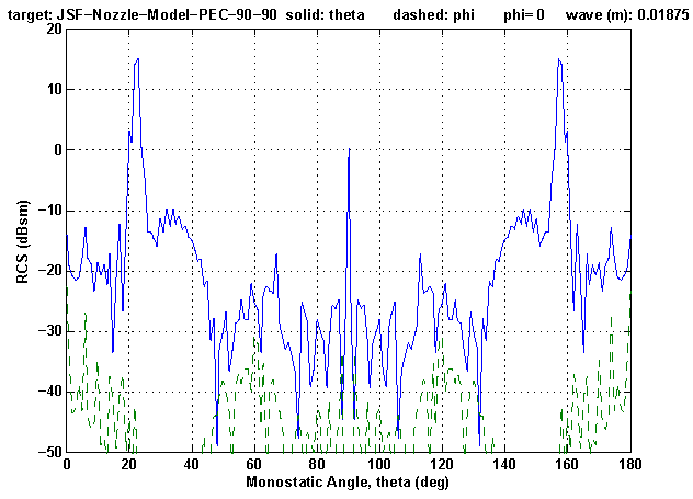
Best case performance was observed in the
Ku-band for threats directly behind the aircraft, with the caveat that
a single lobe with a 1 square metre RCS is seen about the axis of the
nozzle.
|
Imagery
Sources: Author; www.jsf.mil, US DoD.
|
|
Air Power Australia
Analyses ISSN 1832-2433
|
|
![Australia's First Online Journal Covering Air Power Issues [ISSN 1832-2433]](APA/APA-Title-Analyses.png "Australia's First Online Journal Covering Air Power Issues [ISSN 1832-2433]")


 [Click for more ...]")


