|
||||||||||||||||||||||
 |
||||||||||||||||||||||
 |
 |
 |
 |
 |
 |
 |
 |
|||||||||||||||
 |
 |
 |

|
 |
 |
 |
 |
|||||||||||||||
 [Click for more ...]") |
||||||||||||||||||||||
| Last Updated: Mon Jan 27 11:18:09 UTC 2014 | ||||||||||||||||||||||
|
||||||||||||||||||||||


SNR-75M3 Fan Song E Engagement RadarСтанция Наведения Ракет СНР-75 Fan Song E |
|
| Text
by
Dr Carlo Kopp, AFAIAA, SMIEEE, PEng Images by Miroslav Gyűrösi July 2009 Updated April, 2012 Images © 2000, 2009 Miroslav Gyűrösi Text, Line Art © 2009 - 2012 Carlo Kopp |
|
|
|
SNR-75M3 Fan Song E Engagement Radar |
|
Technical Analysis of RSNA-75/SNR-75 Fan Song Engagement Radar |
|
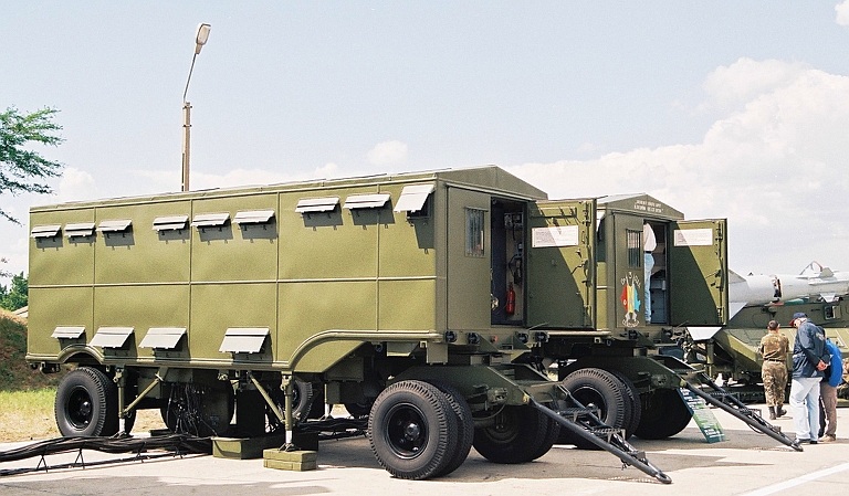
The SNR-75
Fan Song family of radars was employed to provide target fine tracking
and command link guidance for the S-75 / SA-2 Guideline SAM. The radar
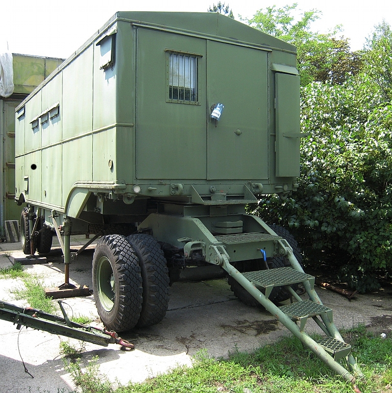
system is packaged in four vans, designated the:
Not depicted is the RV van
which is
the central power supply for the missile battery, providing three phase
400 Hz utility electrical power. The RV van contains:
This arrangement permitted
missile
battery operation without external power, or operation using the local
power grid, regardless of the quality of the local electrical grid.
All of these vans were towed, typically by a general purpose 6 x 6 ZiL or UrAL truck, although the tracked AT-S artillery tractor was often used in the Middle East in soft desert terrain. The missile command post and guidance crew comprised:
|
|
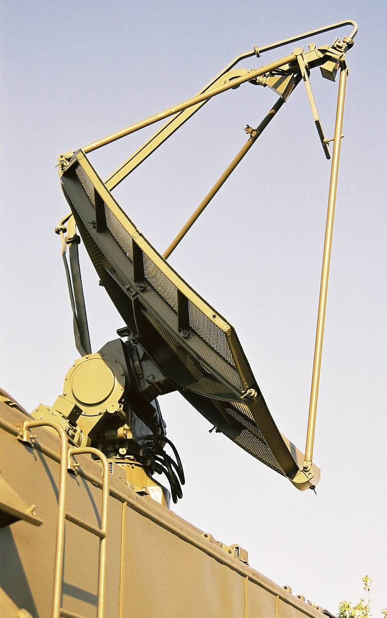
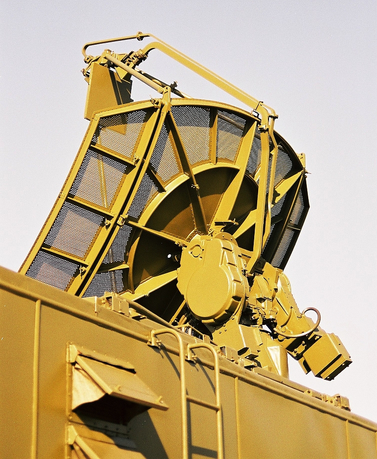
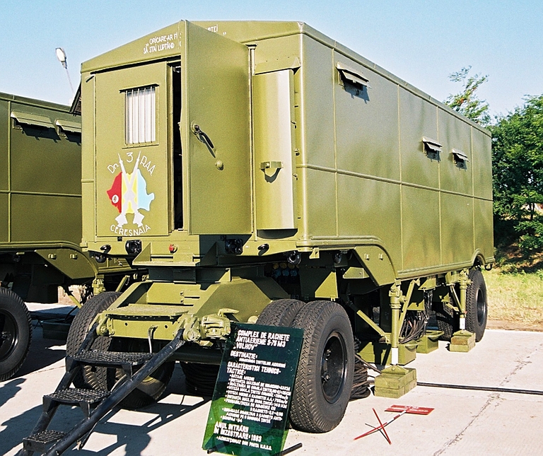
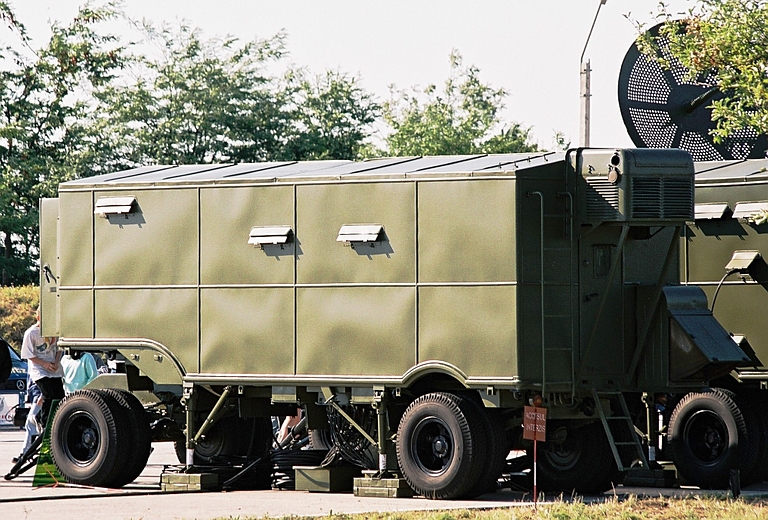
PV Cabin / Radar Head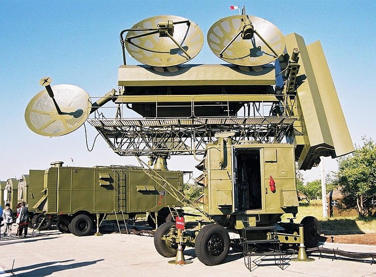 PV
van with
antenna head elevated at ~15° and rotated on the base turntable.
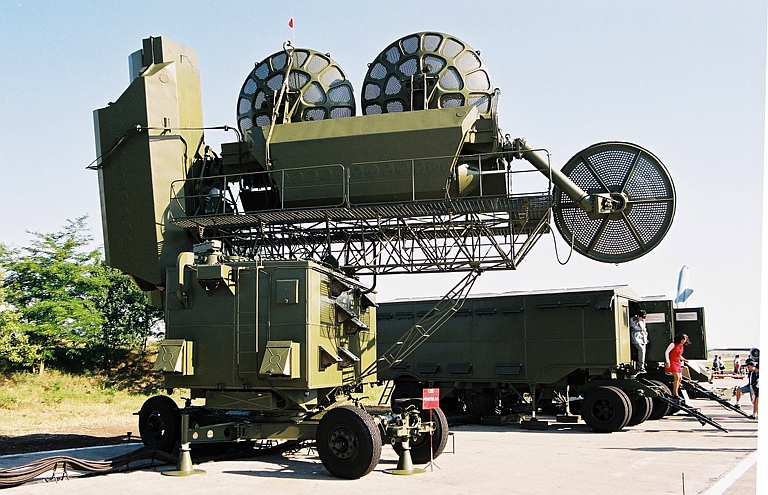 Aft
view of PV van with antenna head levelled.
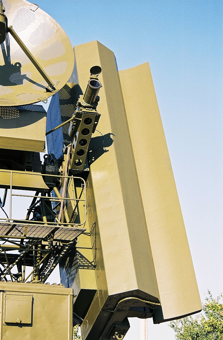 P-11 “Metal Air Lens” trough antenna for
elevation scan, and TV telescope for optical angle tracking under
jamming conditions.
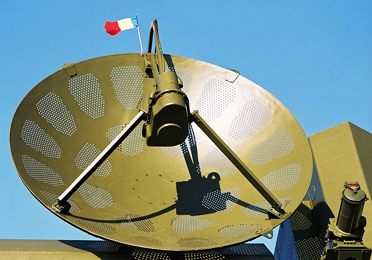 P-13
elevation channel pencil beam antenna and feed.
 P-14
azimuth channel pencil beam antenna and feed.
 P-15/RPK
circularly polarised missile uplink antenna.
|
|
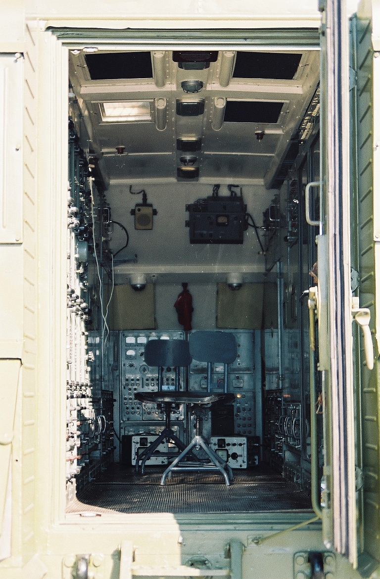
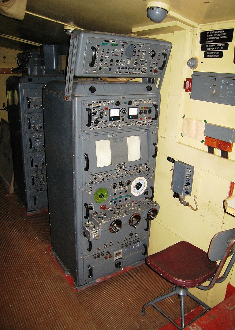
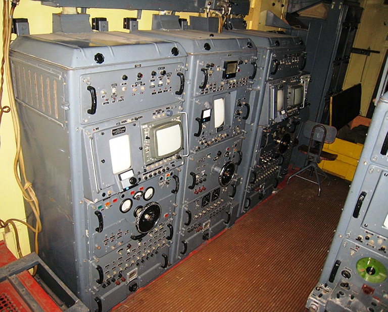
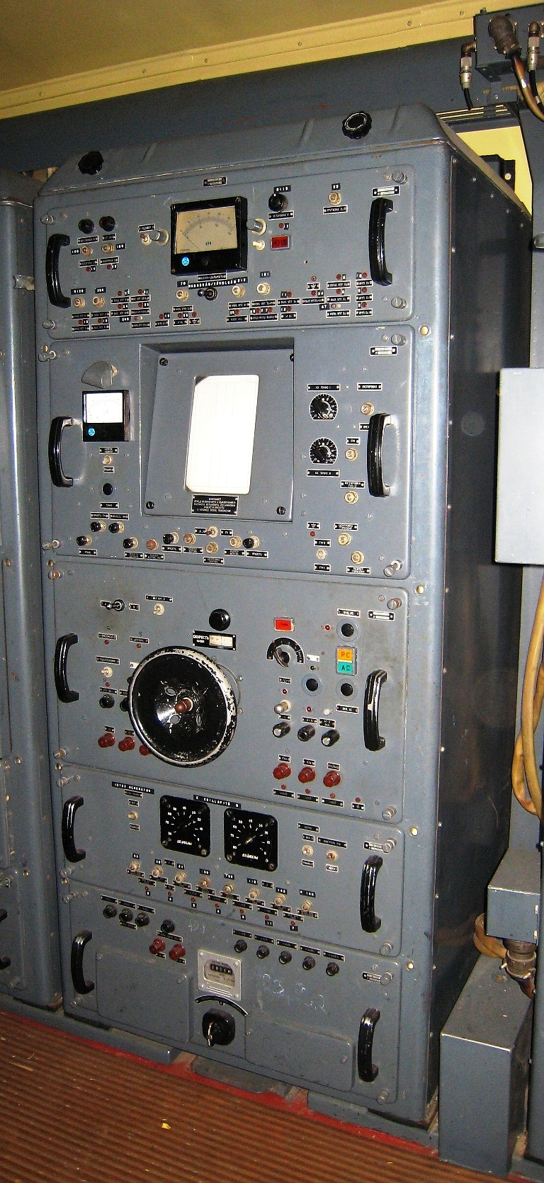
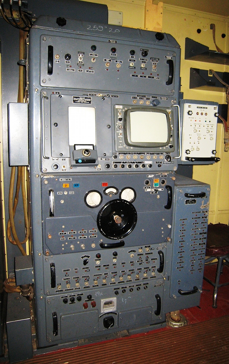
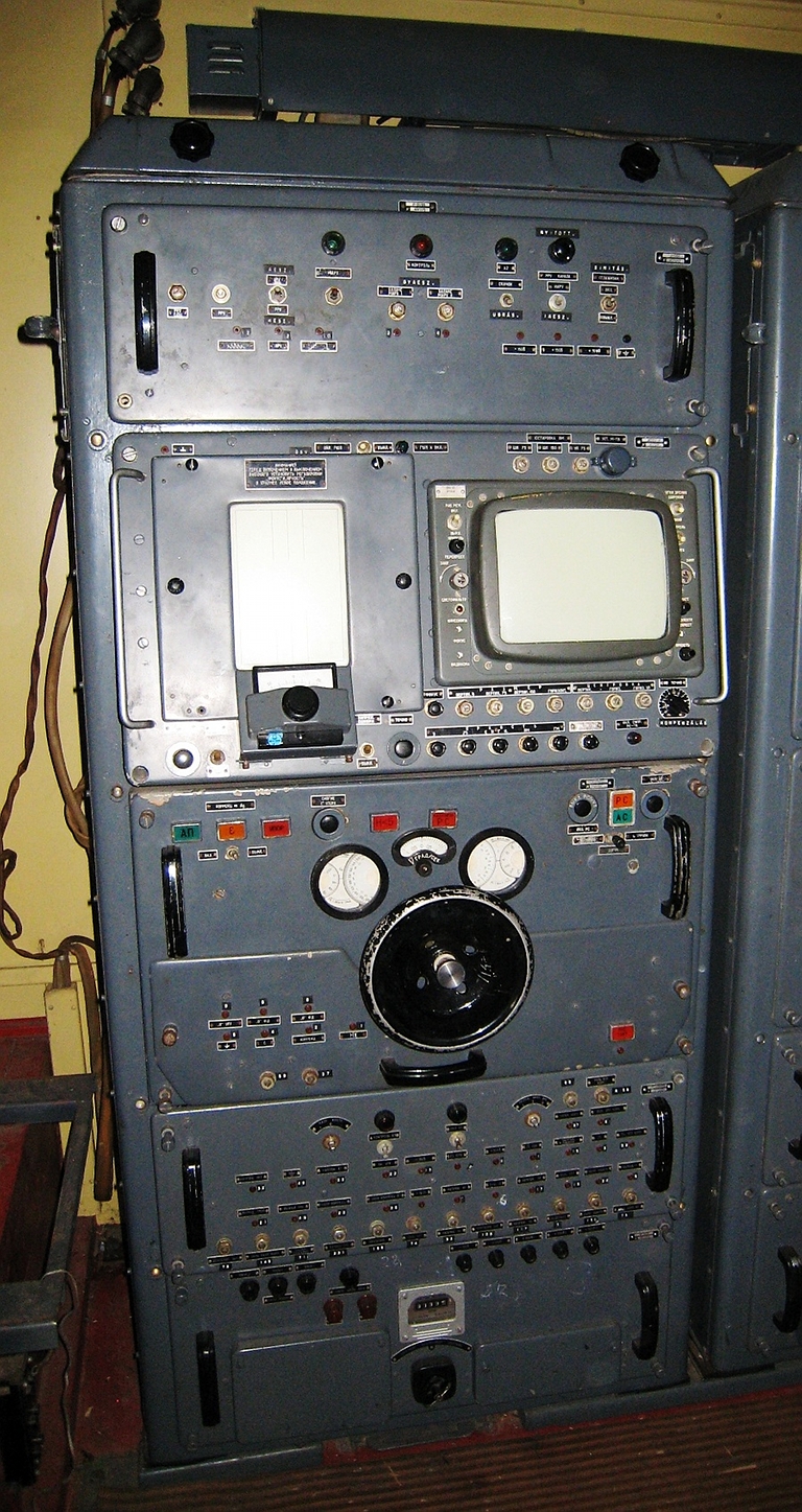
UV Cabin / Operator Stations
|
|
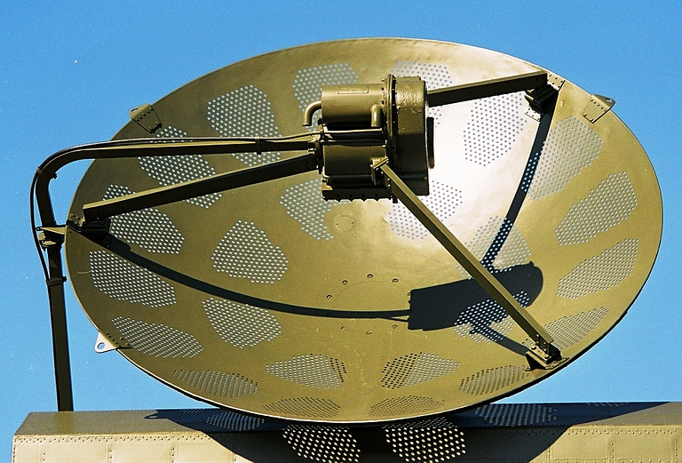
RD-75 Amazonka Rangefinding RadarThe RD-75 Amazonka was a
rangefinding radar incorporated often in late model S-75 / SA-2
Guideline missile batteries. It was slaved in azimuth and elevation to
the boresight of the SNR-75M3 Fan Song and was employed to perform
precision rangefinding when the rangefinding channel in the Fan Song
was degraded or compromised by jamming.
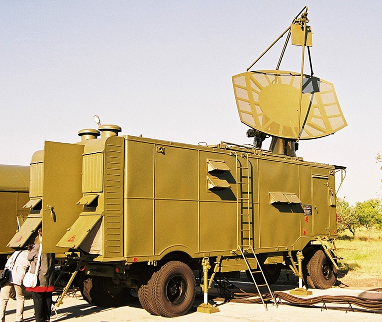 RD-75
deployed configuration.
 RD-75
parabolic section antenna and feeds.
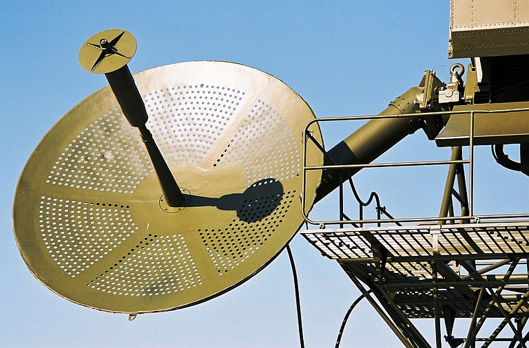
 RD-75 feed horns. The large horn is for
the primary channel, the smaller horn in front of the reflecting planar
screen is for a receive channel. Note the polarisation sensitive
reflector used to improve jam resistance.
 RD-75
waveguide to feed, and antenna drives.
 |
|
| Technical Report APA-TR-2009-0702-A |
|
|
|||||||||||||
|
|
|
|
|
|
|
|
||||||
|
|
|
|
|
|
|
|
||||||
|
|||||||||||||
| Artwork, graphic design, layout and text © 2004 - 2014 Carlo Kopp; Text © 2004 - 2014 Peter Goon; All rights reserved. Recommended browsers. Contact webmaster. Site navigation hints. Current hot topics. | |||||||||||||
|
Site Update
Status:
$Revision: 1.753 $
Site History: Notices
and
Updates / NLA Pandora Archive
|
|||||||||||||
|
|
Tweet | Follow @APA_Updates | |||||||||||
|
|
|||||||||||||
|
|
|||||||||||||