|
||||||||||||||||||||||
 |
||||||||||||||||||||||
 |
 |
 |
 |
 |
 |
 |
 |
|||||||||||||||
 |
 |
 |

|
 |
 |
 |
 |
|||||||||||||||
 [Click for more ...]") |
||||||||||||||||||||||
| Last Updated: Mon Jan 27 11:18:09 UTC 2014 | ||||||||||||||||||||||
|
||||||||||||||||||||||
|
||||||||||||||||||||||
|
||||||||||||||||||||||
|
|
|
|
|
|
|
|
|||||||||||||||
|
|
|
|
|
|
|
|
|||||||||||||||
|
||||||||||||||||||||||
| Last Updated: Mon Jan 27 11:18:09 UTC 2014 | ||||||||||||||||||||||
|
||||||||||||||||||||||
| Heat-Seeking Missile Guidance | |||
|
|||
|
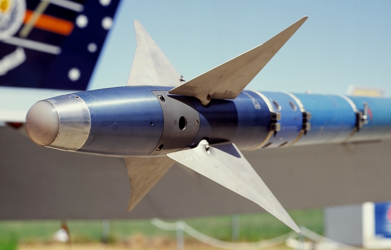
AIM-9M conscan seeker with MgF2 nose window (© 1999 Carlo Kopp).
Air to air missiles (AAMs) differ principally in guidance, the two broad groups being radar guided and heat-seeking or infra-red (IR) missiles. Of the two categories, the second, by virtue of it's simplicity and lower demands on launch aircraft complexity, has become the numerically superior, arming high performance fighters like the F-15 or F-14 operated by frontline air forces, yet also equipping vintage 1950's fighters, defending Third World countries. The initial deployment of heat seeking missiles began in the late 1950's, with the USAF acquiring it's first AIM-4 Falcons and AIM-9 Sidewinders, however, it was not until the Viet-Nam war that the AIM-9 saw widespread use. The weapon was not as successful as expected, reliability was a particular problem, especially with the USN (repeated carrier launches and recoveries - quote ''banging them on the deck after every flight''), but when the missile did work, it was effective, which may be confirmed by a number of NVAF pilots who had the unique experience of a 'Winder entering the tailpipe of their sturdy Mikoyan, resulting in it's subsequent bisection. Current versions of the AIM-9 are a vast improvement, though they are to be replaced by the end of this decade by the ASRAAM - solid state electronics allow for higher reliability and enable the guidance to be ''smarter'' in between discriminating targets and resisting jamming. As their name implies, heat-seeking missiles home on to the hot areas of a target. The target will usually both reflect and emit infra-red radiation, which propagates through the atmosphere, losing it's intensity due to number of effects. This radiation is detected by the missile's seeker head, which, if the conditions are right, will then provide the guidance with the relative position of the target enabling the weapon to home in and destroy the target. In order to fully appreciate the problems involved in creating an effective weapon of this kind, we must examine the behaviour of infra-red radiation, the characteristics of an aircraft as a source of IR energy, the manner in which this energy travels through the atmosphere and finally, how the missile seeker processes it to gain information as to the target's position. Infra-Red Radiation The infra-red is a term used to describe a particular group of electromagnetic waves, those which are longer than visible wavelengths and shorter than microwaves, numerically the band between 0.8 and 1000.0 micrometres. This means that infra-red radiation has very many properties similar to visible light, it can be focussed or diffused, absorbed or reflected. The reason why the IR is so important is that it may be closely associated with heat and it's transfer from bodies. When we heat an object, or a volume of material, we are feeding energy into it - at an atomic level this energy is in the form of crystal lattice vibrations (probably the best way of visualizing the process is to picture an infinite lattice of tiny balls, each connected to it's neighbours by a spring, imagine then what occurs if we tap one of the balls) every atom vibrating about some equilibrium position in the lattice. To make things more complicated, in the physical world, the amount of energy each atom can transfer to it's neighbour is limited to an amount hf (h is Planck's constant and f is the frequency of vibration) which leads to an interesting result - a heated body emits radiation throughout a continuous band of wavelengths, the relative amplitudes (levels) of each wavelength depending on the body's temperature. Graph 1. illustrates this relationship. This means that every object radiates energy, the dominant wavelengths depending on the temperature. As it turns out, objects at temperatures around and below 1200 C radiate mainly in the infra-red band, e in the higher the temperature, the shorter the dominant wavelengths. (note: IR radiation can also be generated by exciting a molecular gas, as the frequencies at which the molecules rotate and vibrate fall into the IR band - this type of radiation forms narrow bands in the spectrum -see TE Dec.1981, Lasers). Sources of IR energy The easiest answer to that question is - any warm or hot object- however, the subject deserves a little more attention. The single greatest source of IR radiation is the sun, however only part of this energy would be available to illuminate the Earth's surface, as large amounts are absorbed and scattered in the atmosphere, particularly by clouds and moisture. The Earth's surface becomes a secondary source of IR, as it is being bombarded both with visible and IR energy from the sun and as a result, is being heated. Any processes releasing heat also lead to the emission of IR. All heat engines ie the internal combustion engine or jet turbines radiate IR from various parts of their structures and also release hot exhaust gases. All warm blooded creatures emit IR. As far as a guidance system is concerned, all IR radiation
from sources other than the target is a nuisance - background clutter
which will lower detection ranges or even swamp the emissions of the
target. Fortunately most of the IR energy emitted by the Earth's
surface
falls into the vicinity of 10 micrometres, whereas the Sun's radiation
peaks in the visible band and reflected off the Earth's surface would
tend to swamp the region above 3 micrometres, hence leaving a window
around 4 micrometres. The sky itself reflects and scatters a certain
amount of IR, though it's intensity is lower than that of the Earth's
surface. 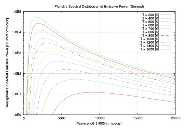 Graph 1. Relative emitted power versus wavelength of emitted radiation for an ideal blackbody radiator. These curves illustrate the relative amounts of IR energy emitted at various wavelengths for varying temperatures, the dominant wavelengths can be seen as becoming shorter with increasing temperatures. (Note: an ideal blackbody by definition radiates equally well at all wavelengths, an aircraft tailpipe is close to a blackbody in a very limited range of wavelengths).
Diagram 2. The Infra-red signature of a fighter aircraft. Here a likely target for a Sidewinder, a MiG-23BM Flogger powered by a 25,000 lb R-29 afterburning turbofan. The aircraft itself both reflects IR from the sun and emits IR from it's hot parts, particularly the afterburner nozzle. The exhaust plume temperature curves illustrate sections through areas of equal temperature, the upper half with lit afterburner, the lower on dry thrust. The lower temperature (cca 100 deg) curves for the afterburning mode extend to a distance greater than 100 metres behind the aircraft. The plume of a turbojet on dry thrust is narrower and hotter than taht for a turbofan, which mixes cool bypass air with the turbine exhaust gasses.An Aircraft as a Source of IR Modern military aircraft are, in spite of the efforts of their designers, abundant sources of IR energy. The principal heat source is the propulsion, as jet engines have an efficiency far below 100%, a considerable amount of energy is thrown away, advertising the aircraft's position. The most intense IR source in a jet aircraft is the tailpipe (afterburner off). The exhaust gas temperature (EGT) of a typical turbojet, ie the J79, is around 950 deg C, newer engines like the F100 have an EGT around 1300 deg C. The highest intensity is thus for wavelengths around 2 to 3 micrometres (for the physics oriented, the tailpipe is modelled as a blackbody, or rather greybody radiator). The exhaust gases leaving the tailpipe form a plume, as they expand and cool. On dry thrust, the tailpipe is the strongest radiator, the plume being cooler, particularly in the instance of high bypass ratio turbojets (F404) or turbofans (F100), where the turbine exhaust gases are mixed with bypass air from the fan. Plume shapes and temperatures vary with engines and operating conditions, diagram 2. illustrates typical temperature curves for a turbofan. Lighting the afterburner causes further radiation of IR, in fact the exhaust plume, around 2000 deg C, then dominates the aircraft's signature, being hotter and physically larger than the tailypipe. (note: at speeds above 2.5M the plume radiance will decrease due to the decreased overall engine pressure ratio). Aside from tailpipe/plume emissions, the hot parts of the engine eg exterior of afterburner nozzle, also radiate. High speed flight will heat the aircraft's skin and the engine will usually heat up parts of the airframe . A further source of emissions is reflected sunlight/IR, conventional paints apparently reflecting around 60%, though the newer low IR greys (USN F-14, F-4, F-18 etc.) reflect around 5 to 15%. A well polished canopy may also reflect enough energy for a lock-on. From the practical point of view, the IR signature of an aircraft is impossible to eliminate, the best one could ask for is a reduction. The use of turbofans reduces the overall EGT and where possible, parts of the airframe may be used to shield the exhaust, as in the A-10, where the tail surfaces screen off the relatively cool exhausts of the TF34s (note: the positioning of the engines makes it impossible to gain a lock-on with a shoulder launched SAM, eg SA-7, until the aircraft has covered a relatively large distance, assuming the aircraft passes over the launch site. ) The use of low reflectance paints and flat canopies (helos) can be of some use. Atmospheric Propagation of IR Radiation The atmosphere basically affects IR energy in three different ways - absorption, scattering and scintillation (for a more detailed treatment see TE Dec.1981, Lasers). Photons of IR wavelengths are absorbed mainly by atmospheric carbon dioxide and water molecules, fortunately for the militarist, this is a quantum physical effect and is confined to particular bands in the IR, leaving transmission "windows". The most important windows in the near IR are centred on 1.6 micrometres, 2.2 micrometres and 3.75 micrometres, the last being the widest at about 1 micrometre, at an altitude cca 5000 m and low water vapour concentrations these allow for up to 95% transmittance at ranges cca 30km (16.5 NMI). If the water vapour concentration increases, scattering becomes noticeable. Scattering occurs when the wavelength of the IR is comparable in size with the scattering particles. Clouds and fog contain droplets around 1 micrometre in size - this results in extremely low transmission throughout most of the IR band. On the other hand, rain droplets are much larger, with the seemingly surprising result that IR transmission through rain is substantially better. Rain is liable to degrade the systems performance, but still allow it to function (at 1.8km / 1 NMI transmittance for light rain is cca 90% and for heavy rain cca 65%). Scintillation is caused by the same effect responsible for the blooming of laser beams, local variations in the atmosphere's refractive index caused by variations in temperature (eg observable flickering of distant images on a well heated bitumen road). This effect isn't particularly important for guidance systems, as the apparent changes in the target's position get smaller and smaller as the weapon approaches the target, once the angular size of the target becomes larger than the size of the apparent changes in position, it can be neglected. The effects of the atmosphere can be summarized as a lowering of the target's intensity over a distance, and the introducing of small position errors at large distances. These two effects basically serve to limit the maximum range at which a guidance system may detect, track and lock on to a target. The Heat-seeking Missile The aircraft as an intrinsic source of IR energy and the reasonably good propagation of IR clearly indicate the potential for relatively simple, accurate short range missile guidance. As the target itself emits all the energy needed for detection and guidance the weapon may be fire-and-forget, without the need for complex and cumbersome fire control and illuminating radar. As a relatively simple system, the weapon may be smaller and lighter, it's fire-and-forget ability makes it then ideal as a dogfight weapon, complementing cannon. This reflects in the widespread use of such weapons, eg the AIM-9J/L with the F-16, the R.550 Magic/Mirage III/F1 or the Israeli Rafael Shafrir used with virtually all IAF fighter aircraft, not to speak of the K-13A Atoll or the AA-8 Aphid used by Warpac air forces. A guided missile can be broken down into three systems, guidance and control, warhead and propulsion, all fitted to an airframe. Propulsion is usually provided by a solid propellant rocket with a burn time of the order of seconds, this is adequate for acceleration to speeds cca 3.5M. The warhead is usually small in weapons of this class, as it is assumed the missile will detonate either on the target or within it, warheads are commonly high explosive/fragmentation types . Most weapons employ a combination of proximity and impact fusing. The guidance and control systems of the missile occupy it's nose section, the guidance senses the position of the target and issues commands to the servoes in the control section which then actuate the control surfaces to achieve the desired flightpath correction. The vast majority of operational IR guided missiles employ a canard control surface/tail stabiliser configuration, the type of canard employed usually betraying the particular emphasis placed during design, eg the stabilising fins fore of the canards on the R.550 serve to prevent stalling at high angles of attack.
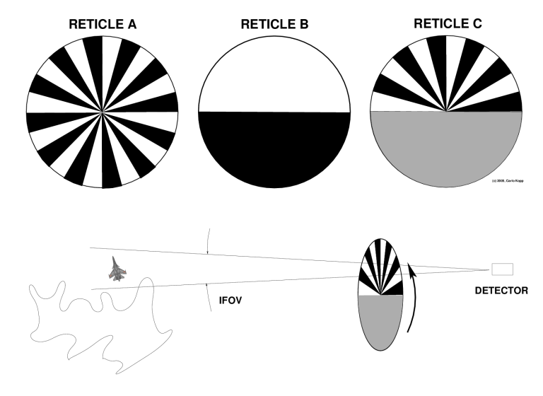
The guidance system itself commonly consists of a window/filter assembly in the nose of the weapon, this serves to select only particular wavelengths of IR, these then enter an optical modulation system, a reticle or chopper, which enables a detector element to receive IR emissions from the target, while rejecting clutter. The output from the detector is processed by signal detection electronics which separate target position carrying information from the clutter present, a computer then employs proportional navigation to generate guidance commands. IR Optical Filters An optical filter is a device, which, by some particular mechanism, allows the transmission of some wavelengths, while suppressing others. The principal reason behind the use of filters in guidance systems is the necessity to suppress background IR radiation, such as reflected solar energy, or thermal radiation from the earth's surface and to enable the guidance to discriminate between various parts of the target's signature, as it wouldn't be very helpful to have a $20,000 missile guide into a ten metre long afterburner plume and detonate without damaging the target. Optical filters used in these applications fall into two broad groupings, absorption filters and interference filters. Absorption filters are characterised by wide bandwidths (width of transmitted band) and are usually employed to suppress large regions, typically sunlight. Interference filters can be designed with extremely narrow bandwidths (less than 0.1 of the wavelength at the band centre) and good transmittance, they have the further advantage of reflecting unwanted energy instead of absorbing it. The physical phenomenon exploited in this instance is interference, an effect which occurs when we add a wave to it's own reflection. Consider a series of layers of transparent material, the layers with alternating refractive indices. If we pass a light wave through these layers it will be partly reflected at each interface between layers, alternate interfaces reflecting in and out of phase. Now if the wavelength of the wave is four times longer than the thickness of the layers, an interesting thing occurs namely the reflections from successive interfaces are all in phase, leading to a very high reflectance for that wavelength. Filters employ layers of varying thicknesses to achieve certain degrees of reflectance for particular wavelengths. Precise filters employ up to a hundred layers, each must have a very accurately defined thickness (for IR less than 1 micrometre), in order to meet the bandpassing specifications. Optical Modulators Probably the most complex individual mechanical assembly in a missile guidance system is it's optical modulator or reticle. It performs two extremely important tasks, providing the system with directional target information and suppressing background IR radiation, In principle, a reticle is a IR transparent substrate with a particular pattern of opaque and transparent fields on it's surface. In operation the reticle is placed between the filter/optics and detector, it's motion relative to the optics results in the chopping of the IR incident on the detector in such a fashion as to enable the electronics processing the detector's output to separate information on the target's direction from background images, typically sunlit clouds. The subject of reticle design is quite complex, to make things more difficult, the military has had most information on the subject classified, however the basic principles may be understood from the following. Diagram 3A illustrates a simple rotating reticle for
background suppression. Consider the reticle to be rotating at a
constant rate, then visualise it passing over the image in it's field
of
view, The chopping action will result in different detector outputs for
the point target and for the cloud. The pulses corresponding to the
target (we assume the target is distant enough to be regarded as a
point
source) may then be easily separated from the rippled pulse
corresponding to the cloud by electronic filtering (a narrow bandpass
filter at the pulse frequency), thus enabling the required
discrimination between the target and cloud.
Diagram 3. Target discriminating and direction finding reticles.
Actual reticles employ very fine patterns, usually with complex wavy or zig-zag fields. Diagram 3B illustrates a reticle configured for the finding of the target's direction. Once again consider a constant rate of rotation and pass it over the target. A pulse is generated during each rotation of the reticle, however the instant in time when the pulse commences depends on the angular position of the target. The time lag or lead of the pulses or phase carries the information as to the target's angular position, this information can be extracted via simple electronic means if we know the position of the reticle as it rotates, which is quite easily accomplished in practice. The third reticle in diagram 3. combines the functions of reticles A and B, providing directional information and background rejection. The upper half is comprised of opaque-transparent fan shaped segments, the lower half is semitransparent with a transmittance equal to the average transmittance of the upper half. When the segmented half passes over the target, the output will contain a series of pulses and some varying output given by the back around, when the semitransparent part passes over the -target the output corresponds to the average brightness of the target and background. The output would resemble B, but with bursts of pulses instead of individual pulses. By electronically filtering out these bursts, we can separate target information from clutter, the phase of the bursts yields the angular direction. The radial distance of the target can be found by examining the amplitudes of the pulses, as the actual image of the target on the reticle is a circle rather than a point. The width of the segments on the reticle is smaller than the circle's diameter, if the circle is near the edge of the reticle a lot of light is passed through, if it is near the centre, very little is passed, causing the observed variation in amplitude. Knowing the angular and radial components of the target's direction, we can easily find the X and Y components with respect to the missile's control axes, a computer can then find the required control deflection for target interception. It may be apparent to many a reader that this system cannot provide target direction information if the reticle axis (missile axis) is pointing directly at the target, actual operational systems employ complicated mechanical systems for the rotation and nutation of the optics and reticle to avoid this. The reticle patterns employed are also quite complex and must be extremely accurate. An alternate method of determining the target's direction would involve an array of detector elements, however the electronics required to separate the target from clutter would be substantially more complex. [Editor's Note 2005: in the nearly quarter century since this was written we have seen Focal Plane Array IR seekers displace the reticle based designs described in this article.] IR Detectors The detector is a device which converts IR energy into some electrical signal, which is then processed by the missile's electronics. As a device, the detector comprises a piece of semiconductor material (the photosensitive element), with antireflective and/or filter coatings and a reflector, which increases sensitivity by reflecting any IR which may have passed through the detector back into it. The two principle types of detector element used are photoconductive and photovoltaic, the former change their electrical resistance when illuminated, the latter generate an output voltage on illumination. An in depth look at the mechanisms responsible for these effects exceeds the scope of this treatment, but some understanding may be gained from the following look at solid state physics. One of the basic conclusions of quantum physics was the fact, that electrons orbiting an atom may have only certain discrete energies, energies other than those corresponding to the given orbits being forbidden. If we examine the electronic structure of a multielectron atom, we find the electrons occupying the outermost orbits are the easiest to remove from the atom, by some external force. If we then take a large number of these atoms and begin to move them together, the orbits begin to interfere with each other with the result, that the previously sharply defined energy levels begin to smear out leading the formation of energy bands rather than levels for large numbers of atoms. The uppermost two levels, the so called valence band and conduction band are of the most interest. The electrical resistance of a material depends on the number of free electrons in the material, the more free electrons, the lower the resistance. In terms of energy bands, an electron must transition from the lower valence band to the upper conduction band before it can be available for conduction as a free electron. The difference in energy between the two bands is called the energy gap (Eg), an electron in the lower band must receive at least this amount of energy to transition up and become free for conduction. One way in which this can happen is when an electron absorbs a photon of radiation with an energy hf larger than Eg. This is basically the effect used in a detector. The energy gap in the semiconductor materials used is usually less than 1 electronvolt, which is close to the energy of IR photons with wavelengths shorter than 10 micrometres. Photons which enter the detector collide with electrons, enabling them to become free and alter the electrical properties of the detector. However the detector must be cooled down to around -200 degrees C, as otherwise the thermal energy of the vibrating atoms would free enough electrons to swamp the effects of the detected IR. Cooling is provided either by a closed circuit low temperature refrigerator, Joule Thompson gas expansion refrigerator or by a thermoelectric refrigerator (early AIM-9J), the lower the temperature available, the higher the sensitivity of the detector. The choice of a detector material depends on the required sensitivity at a given wavelength, that is given by the temperature of the target. The majority of the materials used fall into Selenides, Antimonides and Tellurides, typical IR sensitive materials being Mercury-Cadmium Telluride (HgCdTe) or Indium Antimonide (InSb). Early guidance systems were constrained by the lack of available detector materials to working in the 2.5 micrometre band - as a result the weapons were easily confused by strong sunlight, cloud edges or flares and were not effective if launched at a target head on, as they would rather guide for the plume than the aircraft. Later systems operate in the more convenient 4 micrometre band, which falls into a reasonable transmission window and a region where background IR is fairly low. New weapons such as the GD Stinger employ combined infra-red and ultraviolet band sensors (POST seeker), this enables the seeker to discriminate between targets and countermeasures such as flares, though it's ability to handle IR jamming systems such as flashing IR beacons (Cesium lamps) could be questioned. (Further reading: Hudson R.D. - Infrared System Engineering, Dow R. B.- Fundamentals of Advanced Missiles). Heat seeking missile guidance is, after more than twenty five years of use, anything but obsolete. New technology expands launch envelopes and extends ranges with each new generation. of weapons. Some developments in electronics (consider the recent fabrication of 30 x 30 element arrays of HgCdTe on single mounting chips) may lead to completely different configurations in future weapons, the potential, for improvements is very large.
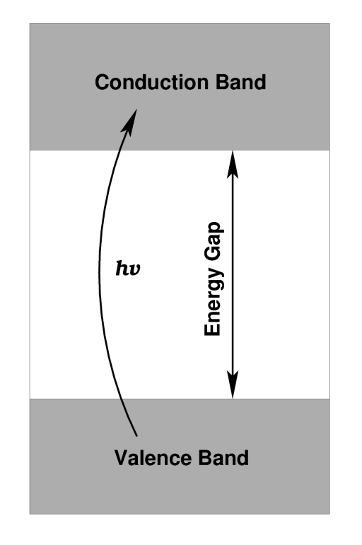 Diagram 4. Energy bands of a pure semiconductor.
If an electron in the lower valence band absorbs a photon hf with an energy greater than the gap Eg, it will transition to the upper conduction band and be available for electrical conduction. Semiconductors sensitive to lower temperatures, such as Mercury-Cadmium Telluride, have energy gaps around 0.2 electronvolts (eV), those sensitive in the near IR, such as Silicon, have gaps around 1eV. ")
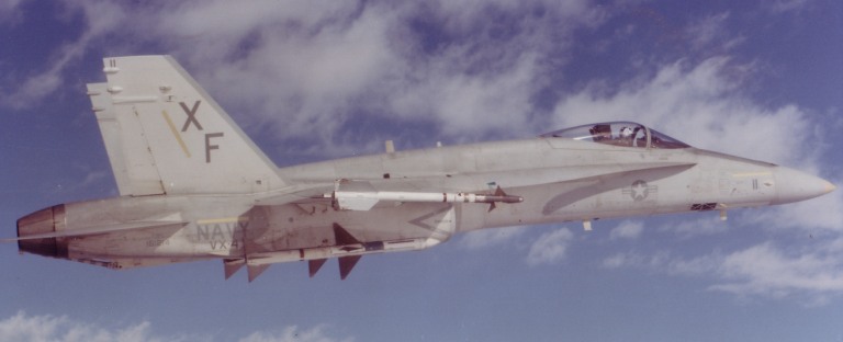
Pic.5. The AIM-9L Super
Sidewinder
is a very late model of the widespread Ford Aerospace Sidewinder, which
saw considerable use in the Viet-Nam war. The missile weighs in at 85
kg, has a cruise velocity of Mach 2 and carries an 11.4 kg
fragmentation
warhead. The weapon has an effective range around 20 km and has been
launched from a variety of aircraft, including USMC AH-1T Sea Cobra
attack helos. The launch aircraft in this instance is a TF-18A combat
trainer. The F-18 is configured to carrry two AIM-9s for close-in
combat, these are mounted on wingtip launch rails., The F-18's
integrated cockpit/fire control automatically conditions radar and HUD
modes for the selected weapon and features a number of auto-lock on
modes, including an off-boresight mode allowing the pilot to lock on to
a target in a tight turn. Earlier aircraft such as the F-4 featured
systems like VTAS (Visual Target Acquisition System), where the missile
seekers were cued by a helmet mounted sight.
|
|||
|
|||||||||||||
|
|
|
|
|
|
|
|
||||||
|
|
|
|
|
|
|
|
||||||
|
|||||||||||||
| Artwork, graphic design, layout and text © 2004 - 2014 Carlo Kopp; Text © 2004 - 2014 Peter Goon; All rights reserved. Recommended browsers. Contact webmaster. Site navigation hints. Current hot topics. | |||||||||||||
|
Site Update
Status:
$Revision: 1.753 $
Site History: Notices
and
Updates / NLA Pandora Archive
|
|||||||||||||
|
|
Tweet | Follow @APA_Updates | |||||||||||
|
|
|||||||||||||
|
|
|||||||||||||


 1982, 2005 Carlo Kopp")