|
||||||||||||||||||||||
 |
||||||||||||||||||||||
 |
 |
 |
 |
 |
 |
 |
 |
|||||||||||||||
 |
 |
 |

|
 |
 |
 |
 |
|||||||||||||||
 [Click for more ...]") |
||||||||||||||||||||||
| Last Updated: Mon Jan 27 11:18:09 UTC 2014 | ||||||||||||||||||||||
|
||||||||||||||||||||||
|
||||||||||||||||||||||
|
||||||||||||||||||||||
|
|
|
|
|
|
|
|
|||||||||||||||
|
|
|
|
|
|
|
|
|||||||||||||||
|
||||||||||||||||||||||
| Last Updated: Mon Jan 27 11:18:09 UTC 2014 | ||||||||||||||||||||||
|
||||||||||||||||||||||
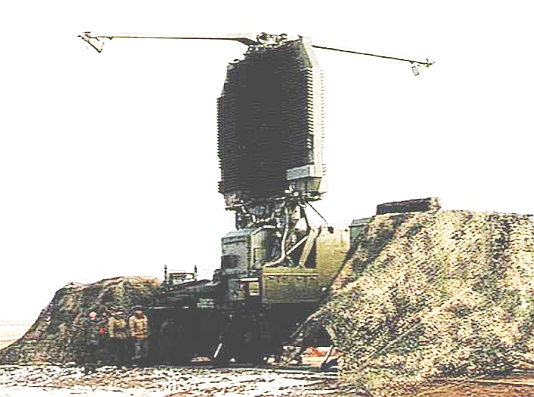
| NNIIRT
1L119 Nebo
SVU / RLM-M Nebo M Assessing Russia's First Mobile VHF AESAs Technical Report APA-TR-2008-0402 |
|||||||||||||||||||||||||||||||||||||||||||||||||||||||||||||||||||||||||||||||||||||||||||||||||||||||||||||||||
|
|||||||||||||||||||||||||||||||||||||||||||||||||||||||||||||||||||||||||||||||||||||||||||||||||||||||||||||||||
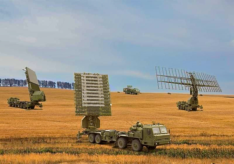 Rendering of Almaz-Antey/NNIIRT 55Zh6ME Nebo ME deployed. The VHF-band component is at the right of the image, the S/C-band component is at the left of the image, the L-band component in the foreground, and the data fusion system, in the background. All components are carried on high mobility BZKT BAZ-6909 series vehicles. At least one hundred of these advanced systems will be acquired for the Russian Federation Air Defence Forces (NNIIRT image).
|
|||||||||||||||||||||||||||||||||||||||||||||||||||||||||||||||||||||||||||||||||||||||||||||||||||||||||||||||||
Background and 1L119 Nebo SVU Development HistoryThe Russian military remains
the principal global user of VHF band military radars. The origins of
this predilection for metre band search and acquisition radars fall
without doubt into the late 1940s, when Soviet designers gained
access to a large volume of captured German equipment. There can be no
doubt that this booty included components and complete systems,
including the VHF band GEMA Wasserman and GEMA Mammut phased array
equipment.
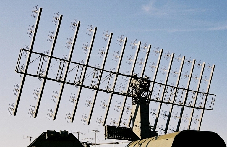
Through the 1950s and 1960s Soviet industry developed and manufactured a wide range of VHF band radars. By far the most numerous were of the Knife Rest and Spoon Rest series, deployed to support Frontal Aviation fighters, and as acquisition radars for the early S-75 Dvina / SA-2 Guideline Surface to Air Missile (SAM) system. The first to be deployed in strength were the P-8 Delfin / Knife Rest A and P-10 Knife Rest B, 2D radars using a now characteristic antenna arrangement with two rows of multiple element VHF Yagi antennas, attached to a rotating horizontal boom. These were soon followed by the more capable 180 kiloWatt peak power class P-12 Yenisei / Spoon Rest A, with an array of 12 Yagis. By the early 1960s the basic P-12 was replaced by the improved P-12M, followed by the P-12MP. Later variants such as the P-12MA and P-12NA introduced the characteristic two van arrangement, and included sidelobe cancellers to deal with clutter and US jamming equipment, a facility for strobed or short burst emissions to defeat US anti-radiation missiles, as well as a remote operator station allowing the radar crew to be located 1,500 ft from the radar head. 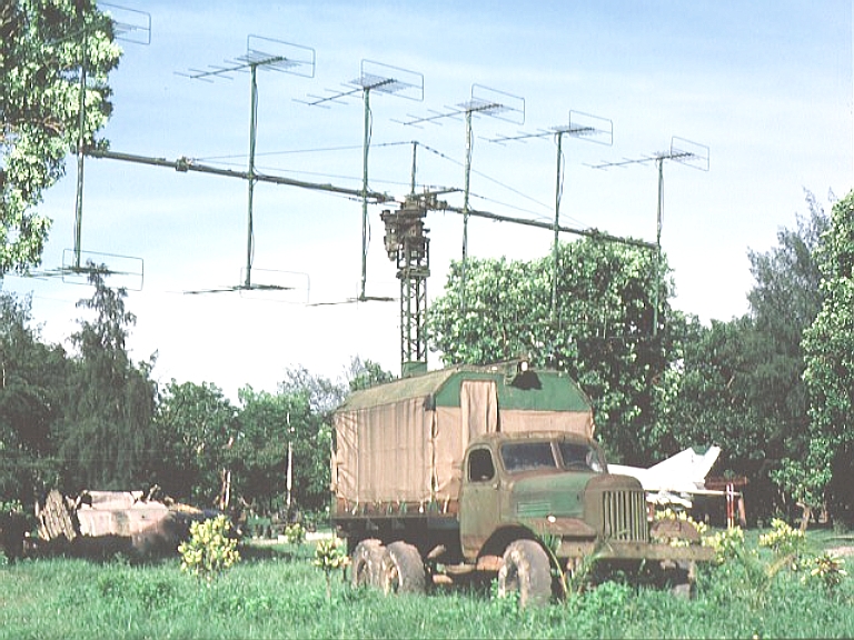 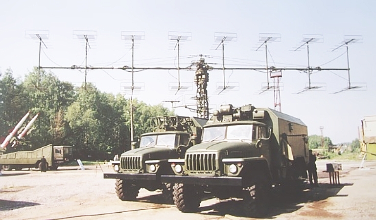 NITEL modernised P-18 Spoon Rest D/E variant (NITEL). The P-12NA was sufficiently different from the baseline P-12, to be redesignated as the P-18 Spoon Rest D, and entered service during the early 1970s. While retaining the general arrangement of the earlier Spoon Rests, the P-18 has more gain with an array of 16 Yagis, while retaining the two van packaging of the late model P-12s. The P-18 was deployed primarily with PVO-SV (Army air defence troops), and also widely exported to Soviet client states and Warsaw Pact nations, with over 3,000 units built according to NNIIRT. By the late 1970s, Soviet air defence commanders sought a more capable mobile 2D VHF radar, and development of the 1L13 Nebo SV / Box Spring was initiated in 1981. The Gorky Institute of Radio Engineering (GNIIRT) was tasked with developing the 1L13 under the leadership of chief designer I.G. Krylov. 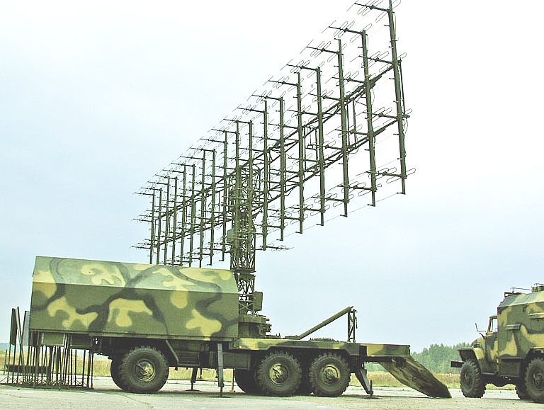 A late model NNIIRT 1L13 Nebo SV / Box Spring VHF acquisition radar. This design replaced the P-18 Spoon Rest D/E in front line Soviet air V-PVO, PVO-SV and VVS defence units following its introduction to service in 1984. Note the sliding hood on the Ural 4320 flatbed truck carrying the antenna system, and the aft facing sidelobe cancelling array. The IFF interrogator is not shown in this image (NNIIRT).
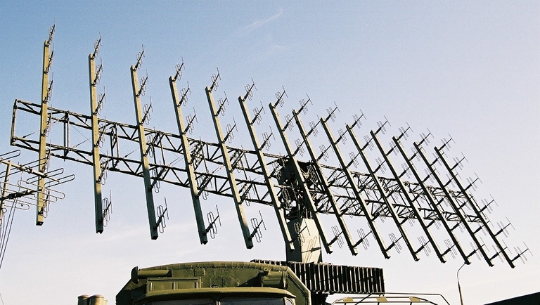
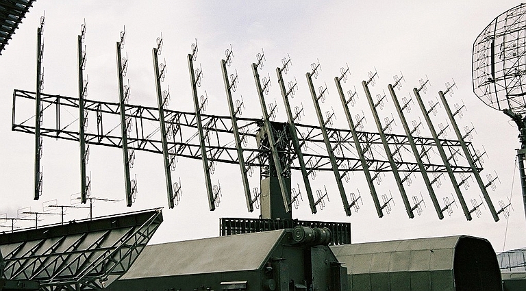
The 1L13 was a large departure from the well trodden evolutionary path of the Knife and Spoon Rest series. Rather than an small array of high gain Yagis, the 1L13 adopted a much larger four row array of 72 lower gain reduced span Yagis, each with a 3/8 folded dipole, single director and looped dipole reflector. The mainlobe width is cited at 6°. Horizontal polarisation was retained. To improve antenna back and sidelobe rejection performance, a rearward facing auxiliary array with three elements was added. The primary array was subdivided into six subarrays of 12 antenna elements each. A combiner network was used to sum the outputs from the six subarrays with the out of phase sidelobe cancelling array output. Russian sources claim that three separate channels are used to provide automatic sidelobe noise jammer rejection but imagery shows only the aft facing array. The antenna array is rotated in azimuth mechanically at 3 or 6 RPM, and also tilted mechanically. Standard operation is at a tilt angle of 9°, with a depressed beam mode at 0° for acquiring low level targets, and an elevated beam mode at 13° for high altitude targets. The high power amplifier is a dual redundant broadband endotron tube, driven by an exciter stage. The backup transmitter can be engaged in eight minutes, or three minutes in an emergency. The peak power rating according to Russian sources is 120 to 140 kiloWatts, with a total equipment power consumption of 29 kiloWatts. The 1L13 has a Digital Moving Target Indicator (DMTI) system design. The coherent output waveform uses a fixed length Barker code. A PRF of 300 Hz is employed. The 1L13 is equipped with a digital signal processor, with a conventional I/Q quadrature two channel arrangement. The radar processing is designed to reject chaff automatically and compensate for wind induced Doppler in chaff clouds, with 50 dB or better ground clutter rejection. The cited receiver sensitivity is -103 dBW. Counter-countermeasures capability is claimed to include pulse to pulse frequency agility. Integration facilities include the capability to merge radar video from external sources, and an automated facility to link to S-band PRV-13 Odd Pair, PRV-16 Thin Skin B, PRV-17 Odd Group heightfinder radars. The 1L13 Nebo SV / Box Spring was accepted into service in 1986, and widely deployed with Soviet PVO-SV, V-PVO and Frontal Aviation VVS units. The system can be deployed or stowed in 40 minutes. A separate IFF interrogator is carried by trailer, and linked to the 1L13 control van. A typical configuration includes a Ural 4320 truck carrying the radar antenna, a Ural 4320 truck with the processing systems and operator consoles, usually towing the IFF interrogator trailer, and a third truck carries the ED2hZO-T230P ZRA diesel generator. While two decades have elapsed since the introduction of the 1L13, it remains in production and offered for export. The current 1L13-3 variant has incremental improvements over the baseline design, with more automation and a two person rather than 4-6 person crew [see table above]. Less known is the fact that the much larger 55Zh6UE Nebo U/UE 3D semi-mobile radar shares a large number of components with the 1L13 series, as both were designed concurrently. 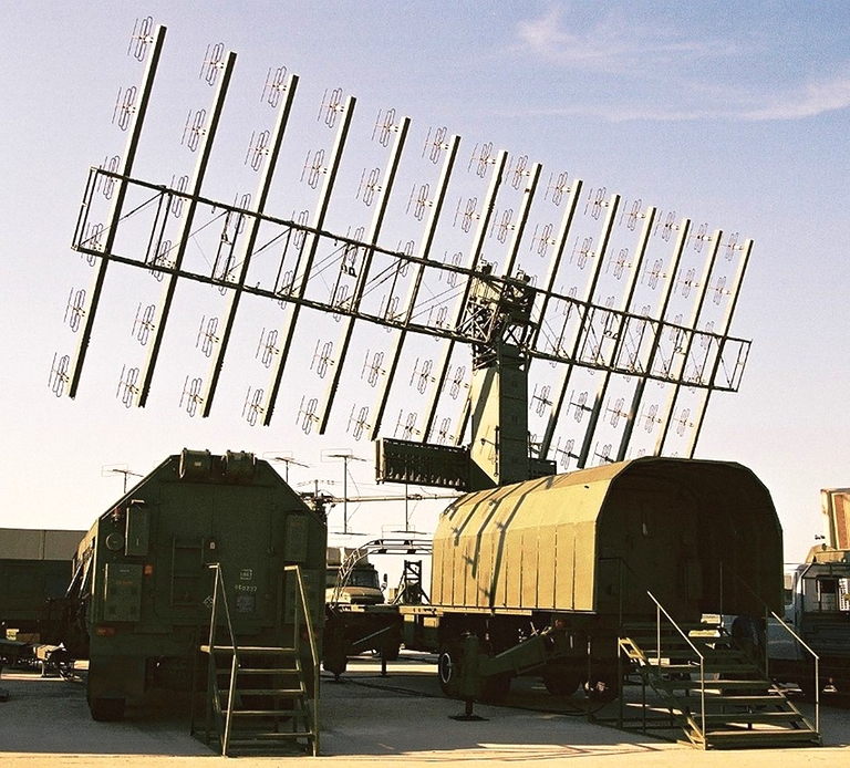 The new three dimensional NNIIRT 1L119 Nebo SVU AESA is an improved new technology derivative of the baseline 1L13 Nebo SV / Box Spring series of VHF radars. Towed by a Ural 4320 tractor, it has much better mobility and reliability than earlier VHF band SAM battery acquisition radars, and with 20 minutes to deploy is only bettered by the S-band 64N6E/91N6E Big Bird series. Stated tracking accuracy is 200 metres in range, 0.5° in azimuth, and 1.5° in elevation, making it suitable as an acquisition radar for the S-300PMU1/2 and S-400 systems. The more recent Nebo M RLM-M derivative improves upon the mobility of the Nebo SVU, and quadruples the power-aperture product achieved (Image © Miroslav Gyűrösi). 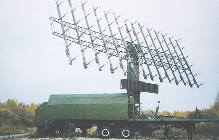 1Л119 Nebo SVU deployed (NNIIRT image). The replacement for the 1L13 series is the 1Л119 Nebo SVU active phased array, first disclosed in 2001. The intent of this new radar was to extend the experience gained with the Nebo SV, and produce a design capable of detecting and tracking Very Low Observable (VLO) and Low Observable (LO) aircraft designs. Like the Nebo SV, this development project was led by Igor Krylov at NNIIRT. He was interviewed by Russian television in 2002, cite: "We can see the Stealth [F-117A] as clearly as any other plane". The Nebo SVU departs from the Nebo SV in many respects. It is a solid state phased array with electronic beamsteering in azimuth and elevation, it is considerably more accurate, it has much better mobility, and incorporates a wide range of improvements. It retains the VHF element design, but uses vertical polarisation. The radar completed its operational certification trials in 2004, clearing the way for Low Rate Initial Production. At least one Russian report claims the Nebo SVU has been exported, but the client has not been disclosed. The radar is being actively marketed for export and has been displayed at a number of Russian and international arms shows. At the Minsk 2007 arms expo, Viktor Ozherelev, head of NNIIRT's department of scientific and technical information, stated: "Now even the Americans have begun to make such [VHF] radars as well, as they understand that their 'stealth' program has failed. These radars can detect aircraft constructed using 'stealth' technology. We have a number of prospects who want to procure a metric band radar."; "The Nebo SVU is the first radar with a solid state active phased array antenna operating in the metric wavelength [VHF] band. Here, each radiating antenna element has its own transceiver [i.e.transmit-receive] module. This makes it possible to achieve very high performance." 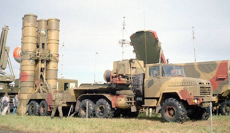 The Nebo SVU is a critically important technological development as it provides a mobile 3D VLO/LO target acquisition and midcourse tracking capability for modern air defence missile systems like this S-300PMU2 Favorit. Deployed as a target acquisition radar for a modern SAM system like the S-300PMU1/2 / SA-20 Gargoyle or S-400 / SA-21 Growler it will significantly complicate engagement tactics for users of VLO/LO fighters, as it can not only deny surprise engagement of the missile battery, but it is accurate enough to provide midcourse guidance data for both Surface Air Missile shots and Air Air Missile shots. Given the Russian predilection for the use of datalinks in networked air defence systems, it is only a matter of time before this capability finds its way into export systems. The Nebo SVU is an important strategic development. It is a modern technology radar by global standards, and its two metre band wavelength will provide it with a robust capability against fighter and cruise missile sized VLO/LO targets. The radar's combination of frequency agility, beamsteering agility, fully digital processing and very good mobility by VHF radar standards sets it apart from two generations of Soviet era VHF radars. If deployed in robust numbers, the Nebo SVU will be capable of frustrating offensive operations by any air force not equipped with an F-22 or better capability. 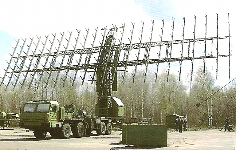 RLM-M component of the Nebo M, based on the VHF band Nebo SVU. This is effectively a true "shoot and scoot" self-propelled derivative of the Nebo SVU demonstrator design, hosted on a BAZ-690915 high mobility chassis, common to the S-400 TEL (NNIIRT). In late 2008, details emerged of a new self propelled and increased power-aperture product derivative of the Nebo SVU, which has been developed as part of the new NNIIRT Nebo M Mobile Multiband Radar System. The RLM-M Nebo M derivative is claimed to be equipped with a more advanced hydraulic stow/deploy mechanism to emulate the "shoot and scoot" capabilities of the 64N6E/91N6E series, an independent 100 kW generator system, and is hosted on a BZKT BAZ-6909-015 8 x 8 all terrain 24 tonne chassis, based on the same vehicle as the S-400 / SA-21 TEL. In late 2011, the Russian MoD announced an order for 100 55Zh6ME Nebo M systems. This analysis will explore the technology in the Nebo SVU/M VHF AESA designs in some detail, with the aim of identifying basic design constraints and performance bounds, and the tactical options available to its users. Performance comparisons are then made between the Nebo SVU and later Nebo M RLM-M system. |
|||||||||||||||||||||||||||||||||||||||||||||||||||||||||||||||||||||||||||||||||||||||||||||||||||||||||||||||||
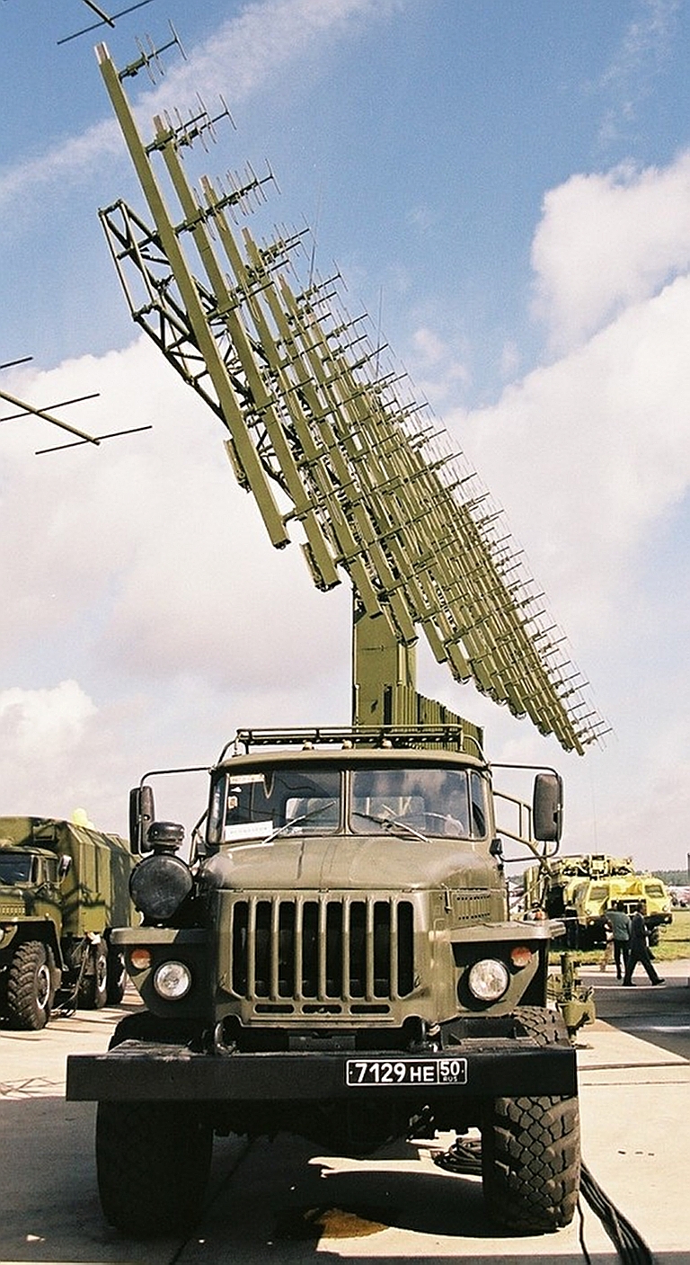
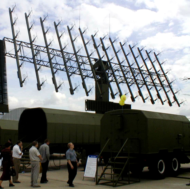
 NNIIRT
Nebo
SVU Ural 4320
tractor towed
semi-trailer variant on display in deployed configuration. Future
variants are likely to employ the same BZKT 8 x 8 series chassis as the
newer Nebo M component radars (Images © Miroslav
Gyűrösi).
 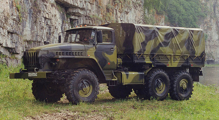 The
Ural
4320-21 is the baseline vehicle for the Nebo SVU tractor
(Avtomobilniy Zavod Ural).
|
|||||||||||||||||||||||||||||||||||||||||||||||||||||||||||||||||||||||||||||||||||||||||||||||||||||||||||||||||
Table 2: Technical
data for
the current export
configuration of the 1L119 Nebo SVU 3D AESA radar
|
|||||||||||||||||||||||||||||||||||||||||||||||||||||||||||||||||||||||||||||||||||||||||||||||||||||||||||||||||
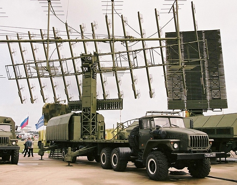
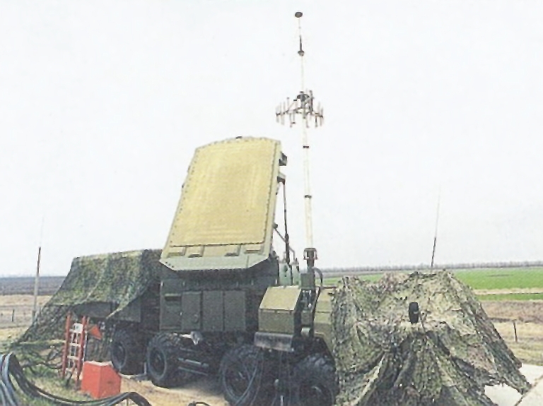
 Stowed configuration. The Nebo SVU
occupies three vehicles. A semitrailer carries the antenna/radar
system, a 6x6 truck the diesel generators, and a 4x4 truck the operator
cabin. The system can be deployed in 20 minutes, which is less than
half of the time required for other Russian VHF radars (NNIIRT).
   Above, NNIIRT 1L119 Nebo SVU on display at MAKS2003. These images are very revealing insofar as they clearly show the combination of 3/8 folded dipoles and directors in a regular grid array. Below, detail of outermost left pair of array element columns, showing 3/8 dipole and director in detail (Images © Miroslav Gyűrösi). 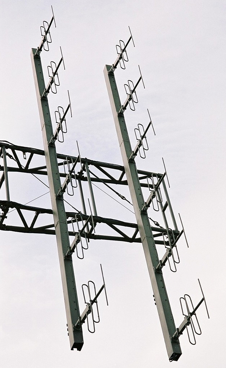 1L119 Nebo SVU Design Philosophy - A Radar Engineering PerspectiveThe impetus for the design of
the latter NNIIRT VHF radars, the 55Zh6 Nebo U and 1L119 Nebo SVU, was
a measure of dissatisfaction with the 2D only mobile 1L13 Nebo SV
series, and earlier VHF radars. These lacked an integral heightfinding
capability and relied wholly on integration with external, typically
S-band, nodding heightfinders. Confronted with the shock of Saddam's
air defence system being utterly impotent against the F-117A, it was
clear to Russian designers that a better long term solution in the VHF
band had to be
found, as the cumbersome two radar solution would be ineffective due to
the severely degraded range of the S-band heightfinding component.
The design rationale for the Nebo U has been discussed in detail in Russian literature, but no such document exists for the Nebo SVU at this time. Therefore we can at best infer the reasoning of Krylov's NNIIRT development team, based on the observable or publicly documented features of the radar. 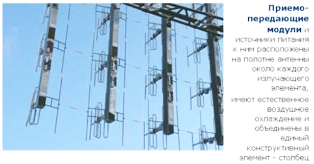 The air cooled Transmit-Receive Modules
are located behind each antenna element. Note that this image shows
reflectors for backlobe suppression added to each of the folded dipole
emitters, these are
absent in images of display equipment (NNIIRT).
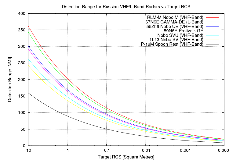
The design is the first ever AESA in the VHF band, with multiple Russian sources elaborating on the use of antenna array mounted Transmit-Receive modules. Unfortunately, no details have emerged on the internal design of these as yet. The similarity in array size, range performance, overall power consumption, operating frequency and general arrangement to the earlier Nebo SV tube powered radar suggests that a peak power rating of the order of 120 to 140 kiloWatts should be expected. With 84 elements this indicates a per TR module peak power rating of 1.4 to 1.7 kiloWatts per module which is readily achievable with mature off the shelf technology. Russian datasheet tables claiming a '20 kiloWatt peak power' are not consistent with cited performance. Commercial VHF band MOSFET transistors rated at 500W are now available in the global market at unit prices of around US$250.00, so building a VHF band TR module rated at 2 kiloWatts with four ganged MOSFETs presents no great difficulty, the only issue being effective cooling. With the low packaging density for a VHF AESA, it is clear that this did not present any obstacle for Krylov and his designers. Western designers have been building kiloWatt class L-band TR modules for well over a decade. Low noise solid state receivers for the VHF band are also a non issue, and the low packaging density requirement for such an array would give the designers considerable freedom in layout. 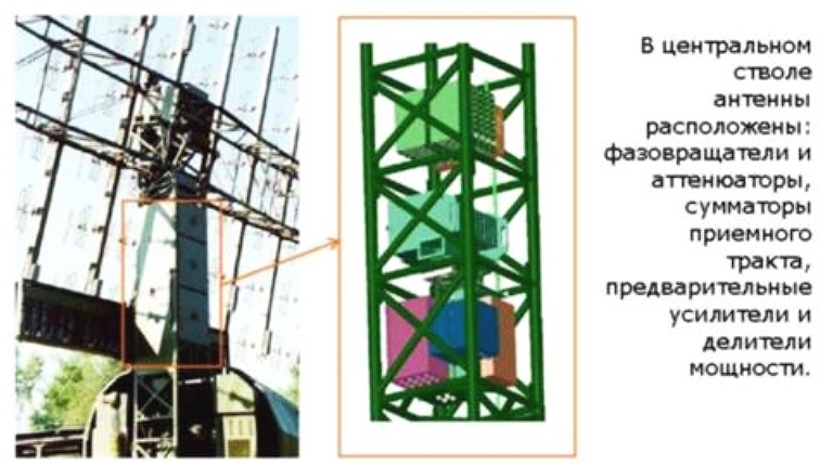 The turntable mounted antenna mast doubles up as a structural mounting for three major RF modules. These include modules containing phase shifters, controllable attenuators, summing networks, exciter stages and power feeds (NNIIRT). 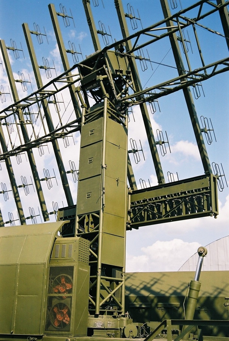 Detail of antenna mast, IFF array, and primary antenna. Note the tilt actuator and joint, and the turntable at the base of the mast (Images © Miroslav Gyűrösi). 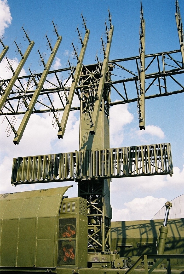 What remains to be disclosed is how NNIIRT designed the phase components for beamsteering control of the antenna, as the claimed module providing this function is quite compact. At such a low frequency a Digital RF Memory (DRFM) style solution might have been adopted, rather than a classical analogue delay line or phase shifter solution - if we assume a carrier frequency of the order of 150 to 220 MHz typically seen in Russian VHF radars, a fourfold sampling frequency of 600 - 880 MHz would be more than adequate to ensure high signal purity. This is again well within the reach of Russia's industry base. If the radar is limited to small beamsteering angles, primarily for angle measurement, the range of phase/delay increments required per element will not be as challenging as for a design having large off boresight beamsteering angle requirements. The radiating antenna element design is a three element hybrid - a vertically polarised two wire 3/8 l folded dipole [Kraus 11-39, 11-61] with a single parasitic director, using additional support frame mounted reflector elements. The well documented dimensions of the Ural 4320 truck and good close up imagery allows a fairly accurate estimation of the wavelength at ~2 metres with a symmetrical ~1 metre array element spacing, ie a regular square lattice. The choice of a 3/8 l folded dipole was clearly driven by its compact size allowing tighter element spacing in the array. Gain is of the order of 3-4.5 dBi per element, but is likely to be reduced by array coupling effects. The choice of vertical polarisation is unusual for a VHF design intended to track aerial targets, and is best explained by the dual role use of the radar for ballistic missile defence purposes, as the shape of ballistic missile targets presents a higher RCS in the vertical polarisation. The 1L119 array design with a regular element spacing has the capacity for growth to a selectable polarisation, with embedded mechanical drives to rotate each antenna element through 90° to select optimal polarisation for a given target detection regime. The principal penalty in the hardware is additional complexity per element, and the need for different processing optimisations for either polarisation. With an electrical motor drive in each element, the rotation and polarisation change could be effected in seconds. The problem of element spacing versus grating lobe performance is interesting in this design. If we assume that the electronic beamsteering capability is used primarily for precision angle tracking of targets near the antenna boresight, grating lobes do not impose quite the burden they do in fixed X-band AESAs, and there is some flexibility in operating frequencies. If the electronic beamsteering capability is used for sector searches, with significant deflection angles off boresight, then grating lobes become a potential problem in the design, and the <1/2 l element spacing rule limits the upper frequency of the design to around 150 MHz, with degraded gain in the 3/8 l folded dipole imposing the lower limit on frequency agility. The range of measurement error in array geometry indicates that the design was sized for larger deflection angles, so ±45° to ±60° off boresight is achievable, subject to aperture foreshortening, sidelobe performance limits, and the shaping of the hybrid two wire 3/8 l folded dipole element mainlobe. Were the design limited to small off boresight steering angles, the element spacing would be greater [1]. With only 84 elements, the 1L119 uses a sparse array, in AESA terms, so highly accurate calibration of module phase/delay and gain are absolutely critical to achieving the intended sidelobe control and beamsteering accuracy for repeatable target angle measurements. As the design is an AESA, digital control of angle/delay and amplitude per element is a given. This also presents considerable freedom of choice in taper (illumination) function across the array, for control of sidelobes. The absence of any auxiliary antennas as used in the 1L13 for sidelobe cancelling can be accepted as proof that the 1L119 uses amplitude control in its antenna channels. Not surprisingly, NNIIRT have not commented on the choice of taper function, only that the radar has 'adaptive sidelobe suppression'. 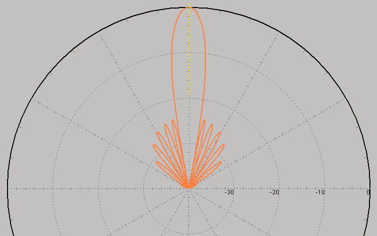 Polar plot for estimated azimuthal plane sidelobe / mainlobe performance using a Chebyshev taper, for a peak sidelobe level of -24 dB (Author). The design may include active jammer nulling by notching the mainlobe, with at least one Russian translation appearing to claim this, but given the quality of so many technical Russian to English translations this could however be a misinterpretation. As an active array this capability could be integrated in the design and simply not disclosed, so from an analytical perspective the safer assumption is that this capability already exists or will exist in a future variant of the design. 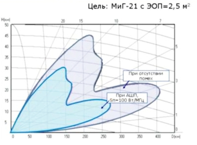 NNIIRT chart showing detection range performance for a 'MiG-21 with RCS=2.5m2' target, in the absence and presence of a jamming signal with a power density of 100 Watts/MHz. Russian data on range performance is consistent, but cited RCS values for identical ranges vary between 1.0 and 2.5 m2. 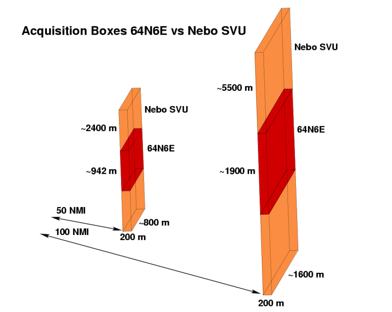 There is some inconsistency in cited error bounds for target tracking. This chart shows worst case performance (range error = 200 m; azimuth error = 0.5° and elevation error = 1.5°), with the best case range error at 100 metres and best case azimuthal error at 0.3°. This performance is of the same order as the S-band 64N6E family of PESAs used as SAM battery acquisition radars (Author). The radar's cited angle measurement accuracies are 1.5° in elevation, 0.5° in azimuth, and range accuracy is 200 metres. This performance is almost identical to the S-band 64N6E Big Bird PESA used as a target acquisition component in the S-300PMU-1/2 Favorit / SA-20 Gargoyle and S-400 Triumf / SA-21 Growler SAM/ABM systems. 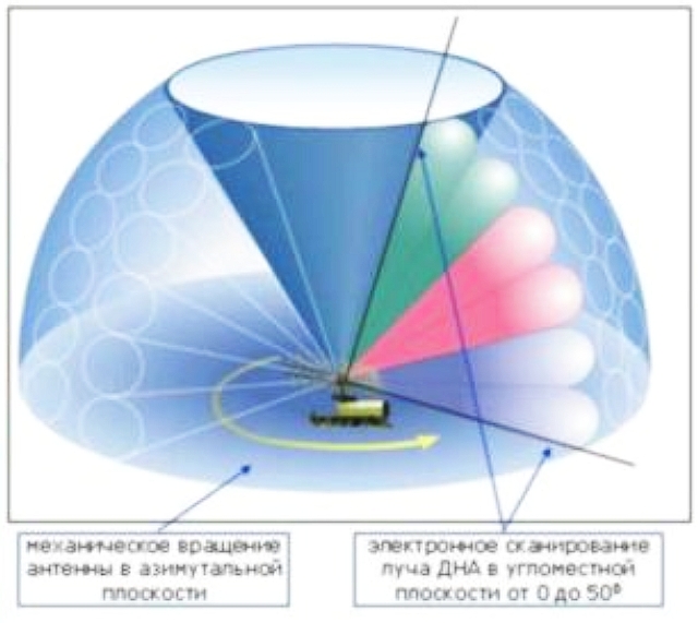 In its 'conventional' search mode the 1L119
antenna array is mechanically rotated and six fixed geometry beams are
generated with an elevation angle of up to 50°. Scan patterns for sector search
modes
have not been disclosed (NNIIRT).
 Russian literature covering the 1L119 describes it as capable of detecting and tracking aircraft and ballistic missile class targets. Tthe antenna can be tilted at least 17° in elevation, the latter cited specifically for 'ballistic missile acquisition'. Ballistic missile target detection is likely to have imposed the choice of vertical polarisation, less than favoured otherwise due to poor ground clutter rejection performance. The antenna can also be rotated at 3, 6 or 12 RPM for aerial target acquisition, or pointed in a fixed direction to cover a specific threat sector. The cited altitude limit for search modes is 100 km, for sector tracking modes it is 180 km. Using a circular sweep pattern the antenna is claimed to be limited to an elevation angle of 25°, but in its fixed azimuth/sector target tracking mode the highest beam elevation angle can be as high as 45° to 50°. If we assume the design is mechanically limited to a tilt angle of 17° this suggests an electronic beam deflection angle in elevation of ±28° to 33°. It follows that a similar bound would apply to horizontal deflection angles, through commonality in delay/phase shifter hardware. Clearly the design will retain all of the DMTI processing features introduced in the 1L13, and Russian literature clearly states that the radar has features for adaptive rejection of ground clutter, precipitation and chaff, including Doppler compensation. Clutter rejection is cited at 45 dB, chaff at 30 dB, and noise jammers at 24 dB, figures which likely understate actual performance. Given that the earlier 1L13 uses Barker codes, it is likely the 1L119 will use the same, or other similar low cross correlation codes. A curious statement in a number of Russian documents is that the radar employs "Complete space-time digital signal processing". This may well be an attempt to explain that the radar is fully digital throughout, or it may be a poor translation of Space Time Adaptive Processing (STAP), only recently adopted in Western radar designs. Is STAP a feasible proposition for a Russian radar designed very recently? Given this radar is a VHF design with a modest sampling rate, and Commercial Off The Shelf (COTS) computing power is not a problem for a design carried by ten tonne Ural 4320 trucks, then the only issue with STAP is the ability of the Russian designers to implement the algorithms required, and whether it is useful enough to justify the effort. Most Western research on STAP is focussed on airborne radars using STAP to adaptively reject ground clutter. For a VHF DMTI the issue is rejection of ground clutter, but also other unwanted effects such as Doppler shifted chaff and weather. At this stage the issue of STAP capability in the 1L119 remains unresolved, but it is a likely capability in this family of radars longer term. There are no fundamental problems with dividing this array into multiple receive path phase centres, since cables are already routed from the TR modules to the central phase control, amplitude control and summing modules. From an analytical perspective the safest assumption is that this capability already exists or will exist in a future variant of the design. Engineering a STAP capability for a fixed ground based DMTI will be easier than doing it for an airborne X-band radar. 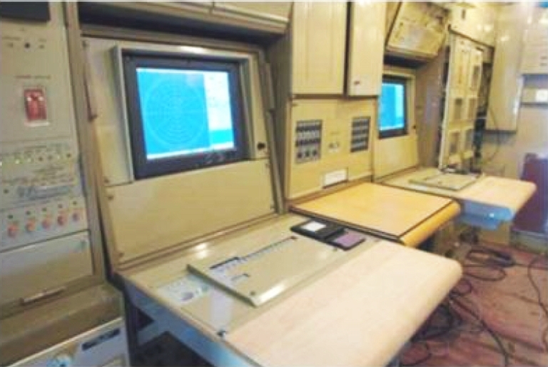 The 1L119 Nebo SVU makes full use of modern COTS technology, with 17 inch LCD displays for operators (above), and flexible digital display presentation (below). Display formats can include geographical data such as borders, air defence zones, and range boundaries (NNIIRT). 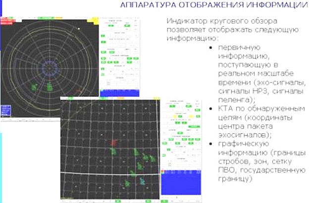 The display system software for the operator consoles and interfacing to the array management processor (array control) was developed initially in the 2000 to 2002 timeframe, using COTS software and hardware, specifically Intel architecture, Linux and С/С++ high level languages, and Xlib, Xt, Xaw, Qt libraries/toolkits. This is the same basic technology used in state of the art US military equipment for this purpose. This also supports NNIIRT claims that the 1L119 is a fully digital system. 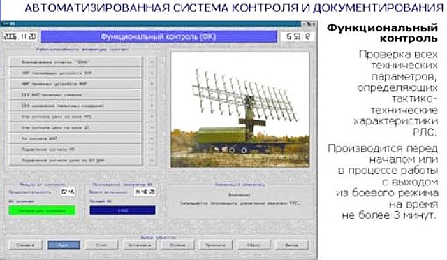 One of the byproducts of the software
based system is an online documentation, management and self test
system. This is intended to further improve the already
exceptionally good availability of the system, compared to earlier
Russian VHF designs.
There are still many uncertainties remaining in understanding the full capabilities of the early production 1L119 Nebo SVU. For instance, the phase/delay control capability and thus maximum off boresight mainlobe angles in azimuth and elevation have not been disclosed. An optimistic estimate is that the design is limited by phase/delay control to modest off boresight angles, used for precision target angle measurement only. A more pessimistic estimate is that the design can achieve an off boresight elevation and azimuth deflection angle of ±45° to ±60° similar to existing US S-band and L-band AESA/PESAs, thus allowing it to perform agile fixed sector searches. While the more optimistic estimate still makes it a highly effective combat capability, the pessimistic estimate would make it exceptionally capable. The basic antenna array design, given sufficiently good engineering, supports both regimes of operation. The safer assumption from an analytical perspective is that the capability for larger electronic beamsteering angles already exists or will exist in a future variant of the 1L119 design. Table 3 Best Case versus Worst Case Capabilities
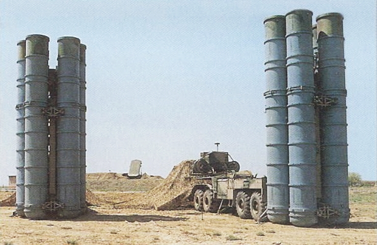
Table 3 maps out the design potential of the 1L119 and the range of capabilities which exist in the current configuration of the design, and would be certain to appear over a 30 year design and production lifecycle. The cited error box of the Nebo SVU is small enough to enable a SAM or AAM with an active or infrared seeker to be flown near enough to the target to acquire it and initiate terminal homing. 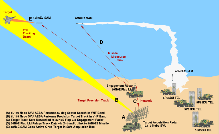 Engaging a VLO/LO target (above) using the 1L119 Nebo SVU as a VHF band acquisition and tracking radar, and the 30N6E Flap Lid as a missile uplink channel (Author).
Whether the Nebo SVU is used as a cheaper substitute for an SA-10/20/21 S-band 64N6E/91N6E radar or paired with a 64N6E/91N6E, the radar has the required performance cue an X-band 30N6E series engagement radar. If these systems are all networked following current Russian practice, the battery's 54K6E series command post can launch the missiles remotely and datalink them to the aimpoint through most of the flight trajectory. When near enough, the missile switches to its own terminal homing seeker to complete the engagement. What the Russians have not disclosed, but is clearly obvious, is that pairing the Nebo SVU and 64N6E/91N6E allows the operators to discriminate between a low observable and conventional radar target and adjust tactics accordingly. If the target is invisible on the decimetric band 64N6E but visible on the VHF band Nebo SVU, then clearly it is low observable, and a missile trajectory flown under datalink control using updates generated by the VHF radar is needed, rather than a conventional engagement sequence where the 30N6E/92N2E locks up the target and completes the engagement autonomously. Missile range performance permitting, this opens up other options such as flying a 'dogleg' curved missile trajectory to effect a beam attack terminal phase, so the missile's seeker is illuminating the less stealthy beam aspect of the aircraft rather than its most stealthy front aspect. 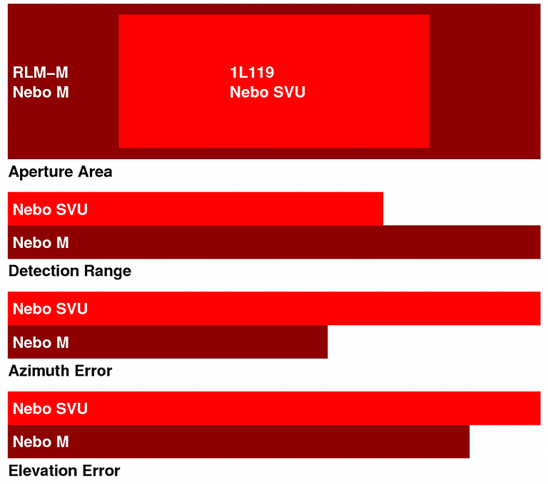
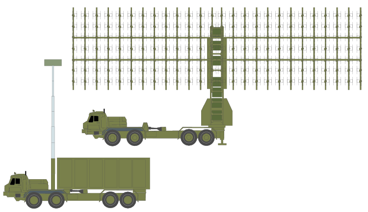 Nebo
M KU and RLM-M
components - a standalone RLM-M would be of a similar configuration
(author).
The improved and larger self propelled Nebo M RLM-M system extends upon the capabilities of the baseline Nebo SVU design. Parametric analysis of performance suggests a 40 percent range improvement over the Nebo SVU if equal TR module power ratings apply, more powerful later generation modules would further improve range. Angular error in azimuth is almost halved, refer Table 4, further increasing the potential of the design for midcourse SAM guidance. In conclusion, the world's first mobile VHF AESA presents a credible capability and introduces all of the refinements seen in modern L-band and S-band acquisition radars into a VHF band design. The claims of a viable capability against conventional VLO/LO designs should be taken seriously [2]. The 1L119 Nebo SVU and RLM-M Nebo M will provide a credible capability for a range of roles, including their use as battery target acquisition radars for the S-300PMU-1/2 / SA-20 Gargoyle and S-400/S-400M / SA-21 Surface to Air Missile systems. As the design has considerable growth potential, it may remain in ongoing development and production for decades [3]. |
|||||||||||||||||||||||||||||||||||||||||||||||||||||||||||||||||||||||||||||||||||||||||||||||||||||||||||||||||
Endnotes[1] Grating lobe chart for ESA analysis (as per Stimson, p483). Assuming the first grating lobe is at 90° off boresight, the element spacing constrains the maximum off boresight deflection angle thus: 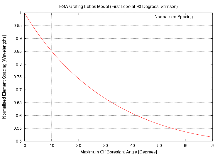 [2] For
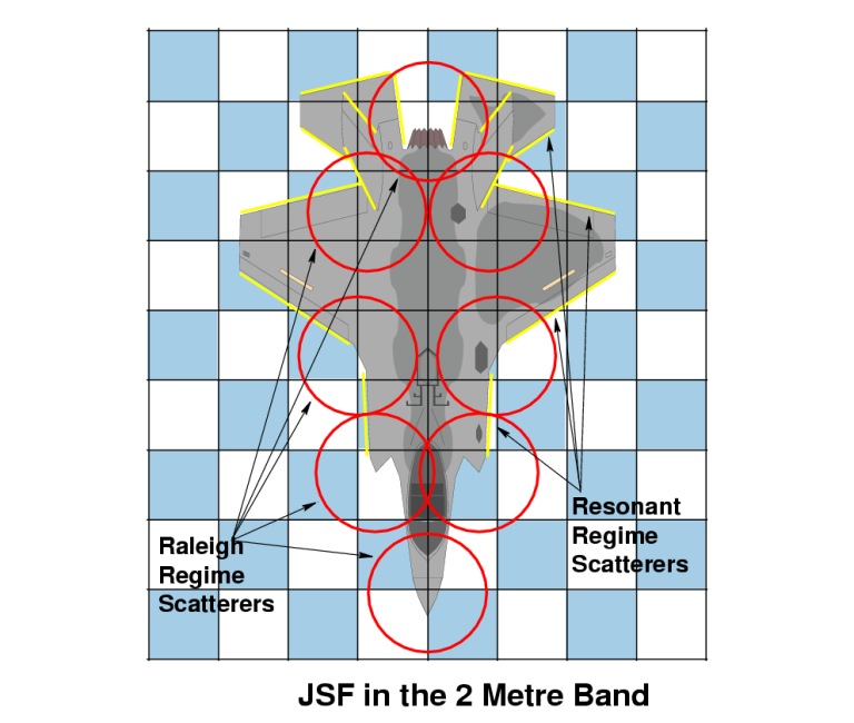
instance,
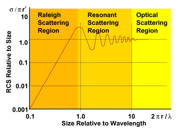
let us consider the F-35 JSF in the 2 metre band favoured by
Russian VHF radar designers. From a planform shaping perspective, it is
immediately apparent that the nose, inlets, nozzle and junctions
between fuselage, wing and stabs will present as Raleigh regime
scattering centres, since the shaping features are smaller than a
wavelength. Most of the straight edges are 1.5 to two wavelengths in
size, putting them firmly in the resonance regime of scattering. Size
simply precludes the possibility that this airframe can neatly reflect
impinging 2 metre band radiation away in a well controlled fashion.
 The only viable
mechanism for reducing the VHF band signature is therefore in
materials, especially materials which can strongly attenuate the
induced electrical currents in the skins and leading edges. The physics
of the skin effect show that the skin depth is minimised by materials
which have strong magnetic properties. The unclassified literature is
replete with magnetic absorber materials which have reasonable
attenuation performance at VHF band, but are very dense, and materials
which require significant depth to be effective if lightweight. The
problem the JSF has is that it cannot easily carry many hundreds of
pounds of low band absorber materials in an airframe with borderline
aerodynamic performance. Some technologies, such as laminated photonic
surface structures might be viable for skins, but the experimental work
shows best effect in the decimetric and centimetric bands. Thickness
again becomes an issue.
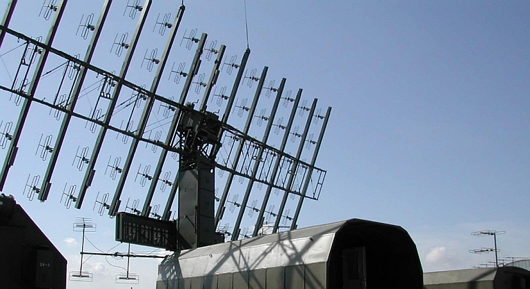
The reality is that in conventional decimetric to centimetric radar band low observable design, shaping accounts for the first 10 to 100 fold reduction in signature, and materials are used to gain the remainder of the signature reduction effect. In the VHF band shaping in fighter sized aircraft is largely ineffective, requiring absorbent materials with 10 to 100 fold better performance than materials currently in use. In the world of materials, getting twice the performance out of a new material is considered good, getting fivefold performance exceptional, and getting 100 fold better performance requires some fundamental breakthrough in physics. [3] Another consideration, peripheral to the design of the radar itself, is its influence on other nations developing products in this area. It is already evident that China's CETC has been heavily influenced by the 1L13/1L119 in the development of its JY-27 VHF band radar equipment [Click for more ...]. 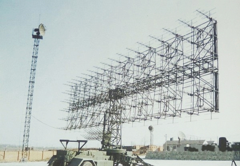 The
CETC JY-27 is a recent
Chinese design which is clearly influenced by the 1L13 Nebo SV and
1L119 Nebo SVU.
|
|||||||||||||||||||||||||||||||||||||||||||||||||||||||||||||||||||||||||||||||||||||||||||||||||||||||||||||||||
AcknowledgmentsThe author is indebted to all parties in Australia and overseas who reviewed the draft of this paper, for their cogent comments and input. |
|||||||||||||||||||||||||||||||||||||||||||||||||||||||||||||||||||||||||||||||||||||||||||||||||||||||||||||||||
References
|
|||||||||||||||||||||||||||||||||||||||||||||||||||||||||||||||||||||||||||||||||||||||||||||||||||||||||||||||||
Bibliography
|
|||||||||||||||||||||||||||||||||||||||||||||||||||||||||||||||||||||||||||||||||||||||||||||||||||||||||||||||||
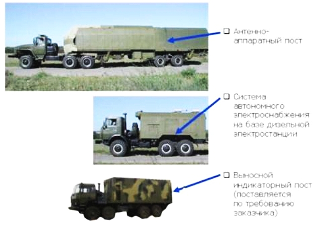
Annex A 55Zh6ME Nebo M Self
Propelled Radar System Components
|
|||||||||||||||||||||||||||||||||||||||||||||||||||||||||||||||||||||||||||||||||||||||||||||||||||||||||||||||||
|
Technical Report APA-TR-2008-0402 |
|||||||||||||||||||||||||||||||||||||||||||||||||||||||||||||||||||||||||||||||||||||||||||||||||||||||||||||||||
|
|||||||||||||
|
|
|
|
|
|
|
|
||||||
|
|
|
|
|
|
|
|
||||||
|
|||||||||||||
| Artwork, graphic design, layout and text © 2004 - 2014 Carlo Kopp; Text © 2004 - 2014 Peter Goon; All rights reserved. Recommended browsers. Contact webmaster. Site navigation hints. Current hot topics. | |||||||||||||
|
Site Update
Status:
$Revision: 1.753 $
Site History: Notices
and
Updates / NLA Pandora Archive
|
|||||||||||||
|
|
Tweet | Follow @APA_Updates | |||||||||||
|
|
|||||||||||||
|
|
|||||||||||||


