|
||||||||||||||||||||||
![Australia's First Online Journal Covering Air Power Issues [ISSN 1832-2433]](APA/APA-Title-Analyses.png "Australia's First Online Journal Covering Air Power Issues [ISSN 1832-2433]") |
||||||||||||||||||||||
 |
 |
 |
 |
 |
 |
 |
 |
|||||||||||||||
 |
 |
 |

|
 |
 |
 |
 |
|||||||||||||||
| Last Updated: Mon Jan 27 11:18:09 UTC 2014 | ||||||||||||||||||||||
|
||||||||||||||||||||||
|
||||||||||||||||||||||
|
||||||||||||||||||||||
|
|
|
|
|
|
|
|
|||||||||||||||
|
|
|
|
|
|
|
|
|||||||||||||||
| Last Updated: Mon Jan 27 11:18:09 UTC 2014 | ||||||||||||||||||||||
|
||||||||||||||||||||||
| Assessing Joint Strike Fighter Defence Penetration Capabilities |
||||||||||||||||||
|
||||||||||||||||||
 |
||||||||||||||||||
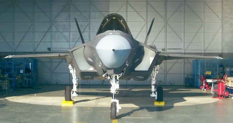
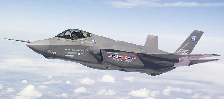 The evolution of the JSF design from the X-35 demonstrators to the F-35A/B/C SDD configuration has seen significant changes to the aircraft's shaping, critical to its stealth performance. While the design of the inlets was improved, the lower fuselage design is now inferior to the original X-35 configuration. The latter has important implications for the JSF's ability to survive when penetrating modern Integrated Air Defence Systems (Image via Air Force Link). |
||||||||||||||||||
|
||||||||||||||||||
|
|
||||||||||||||||||
|
Recent
public
claims
about Joint Strike Fighter defence penetration
capabilities bear remarkable similarities to earlier and continuing
claims about this
aircraft’s air combat capabilities, and affordability. In all
instances, broad
generalizations have been made, which essentially argue that the Joint
Strike Fighter can defeat advanced Russian developed weapon systems now
proliferating on the global and Pacific region stages. Readers of at
least one document are left to infer that these systems include
variants of the Almaz-Antey S-300PMU1 and S-300PMU2 Favorit, both
labelled as “SA-20 Gargoyle” in the NATO naming system.
Especially interesting are claims that the Joint Strike Fighter can penetrate modern integrated air defences, because this was not a stated initial operational requirement when the program was launched during the 1990s, and also because this role is considered a challenging task for the more capable and larger F-22A Raptor, designed from the outset for defence penetration and lethal defence suppression. No less interesting are claims that the Joint Strike Fighter has stealth performance equal to or better than the F-22A Raptor, moreso given the much less disciplined shaping of the Joint Strike Fighter airframe. Given the unusual nature of these claims about the Joint Strike Fighter, it is appropriate to test them critically against what we know about advanced Russian developed Integrated Air Defence Systems (IADS) and the basic design limitations of the Joint Strike Fighter and existing designs such as the F-22A Raptor. Advanced Russian Developed IADSWhen the Soviet Union collapsed during the early 1990s, it possessed the largest and most dense IADS globally, equipped with some of the most advanced and longest ranging Surface to Air Missile (SAM) systems in existence. Despite its depth, density and enormous geographical extent, this IADS was readily penetrated by the US Air Force’s F-117A Nighthawk stealth fighter, which was specifically built to defeat this system. The B-2A Spirit stealth bomber, at that stage in advanced development, was also designed to penetrate this IADS and its then planned successors with virtual impunity. The Soviets deployed their earliest SAM systems during the 1950s, and by the 1960s were integrating their SAM batteries to form an IADS, in which search and acquisition radars, as well as battery engagement radars, provided geographically overlapping and often highly redundant coverage. The aim of this design philosophy was to ensure that even if NATO defence suppression aircraft were capable of killing specific radar systems, there was sufficient overlap in coverage to make it extremely difficult to punch holes in the IADS, to permit penetration by conventional combat aircraft. By the early 1990s the Russian air defence paradigm was mature and well studied, both by the Russians and their former opponents in the West. Several basic principles were implicit and well implemented in Russian designs, especially in the later generation of radars and missile systems:
The initial operational debut of the F-117A in Desert Storm was a major embarrassment for the architects of the Soviet IADS model. The F-117As easily evaded Soviet and French supplied microwave radars allowing them to penetrate undetected and unchallenged, and after hitting their targets, cleanly egress the defended airspace. The imperative to make all Soviet radars and missile batteries mobile, or semimobile, had driven Soviet designers into the microwave S-band and X-band, which are most susceptible to stealth shaping and radar absorbent materials. Since 1991, Russia’s industry and research institutes have invested much intellectual capital and effort to overcome remaining weaknesses in the inherited Soviet model. These are reflected in a range of increasingly frequent design characteristics and deployment techniques in more recent Russian designs:
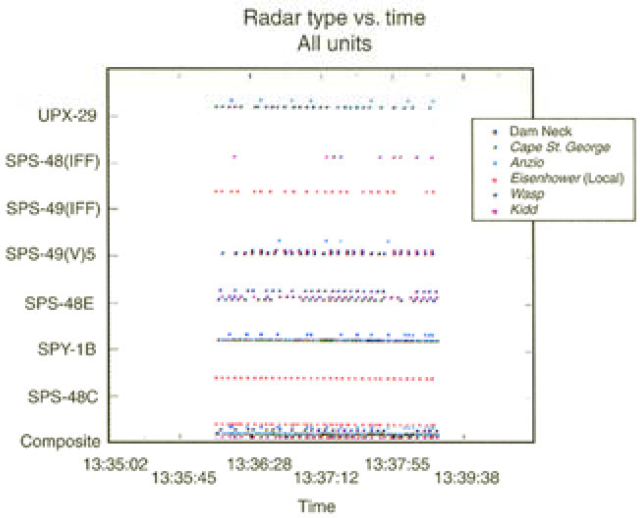
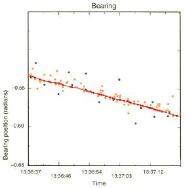
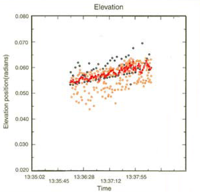
Systems built around these eight ideas are now in production and being actively exported by Russian industry on the global stage. Therefore any IADS which a Western air force must defeat post 2010 may be constructed in part, or wholly, around the fusion of the Soviet era and post Soviet era IADS concepts. A modern post 2010 IADS constructed using Russian, Chinese, or a mix of either components, will be built around these ideas which are part of the doctrinal and training packages which the Russian industry exports with its products. China’s industry has followed Russian thinking almost literally, to the extent of producing a number of clones or direct analogues of Russian designs. An important observation is that when we consider defeating a SAM system such as the S-300PMU1/PMU2 / SA-20 or S-400 Triumf / SA-21, we must think in terms of not only defeating the missiles and their engagement radar, but defeating all of the supporting systems, the deployment model / doctrine and the IADS architecture being used. Defeating one component of such a system does not necessarily defeat the system as a whole, or even the missile battery itself. The Russian approach to IADS architecture is centred in the classical “System of Systems” model where the capability of subsystems is maximised to, in turn, maximise the overall capability and robustness of the IADS. This is very different from the contemporary Western view of the “System of Systems” model, where subsystems such as combat aircraft are intentionally reduced in capability, using “System of Systems” model as a justification for such choices. Russian doctrine for constructing an IADS follows from the Kammhuber model, which is centred on producing geographically overlapping radar and missile system coverage. A modern “SAM belt” is constrained by the very same geometrical coverage considerations applied in the design of the very effective 1943 “Kammhuber Line”. The result is that staggered belts of radar sites are employed, to ensure that a penetrating aircraft must get past two or three missile batteries to break through these defences. The geometry problem is in fact no different to that found in providing reliable cellphone tower coverage. The composition of contemporary and future IADS which Western aircraft will need to defeat will vary, and will comprise mostly variants of Soviet/Russian Almaz S-300P series of area defence SAM systems, direct equivalents of the US Patriot system. At this time the earliest Almaz S-300P/PT / SA-10A systems remain in use in Russia, but are being progressively replaced or upgraded. The SA-10A Grumble is a semimobile system armed with command link guided 5V55 series missiles, deployed on towed 5P85 Transporter Erector Launchers (TEL). The X-band 5N63/30N6E Flap Lid A engagement radar is either towed or elevated on a semimobile 40V6M/MD mast system. Long range high altitude acquisition is provided by the towed semimobile S-band 36D6/ST-68/68U Tin Shield radar, often also mounted on a 40V6M mast. Low altitude target acquisition was provided by the 5N66/76N6 Clam Shell continuous wave radar usually mounted on a 40V6M/MD mast. By the mid 1980s the “self propelled” SA-10B or S-300PS was introduced. This variant was designed with mobility in mind so that the 30N6E battery engagement radars and 5P85D/S TELs could “shoot and scoot” in 5 minutes. It was soon followed by an improved variant, designated the SA-10C or S-300PM. By the early 1990s the S-300PMU export variant of the S-300PS was sold to China and North Korea, using much the same semi-mobile acquisition radar suite as the SA-10A/B. The next important evolution in this series was the S-300PMU1 or SA-20 Gargoyle. While it retained the semi-mobile Clam Shell and Tin Shield, it introduced the new high mobility S-band phased array NIIIP 64N6E1 Big Bird series acquisition radar. The Big Bird could shoot and scoot in 5 minutes and provided many of the capabilities until then seen only in the US SPY-1 Aegis system. It also introduced the new 48N6E series of missiles, which used like the Patriot Track Via Missile (TVM) guidance to improve countermeasures resistance. 30N6E1 Tomb Stone engagement radar was an evolution of the Flap Lid series. The S-300PMU2 Favorit, also designated SA-20, saw further incremental upgrades to the systems, longer ranging 48N6E1 missiles, and improved software and integration capabilities. The SA-20 was the first variant to introduce, as an option, the L-band LEMZ 96L6 Cheese Board acquisition radar, in fully mobile or mast mounted semi-mobile configurations using the 40V6M/MD. The system also introduced the capability to control 5N62 Square Pair engagement radars and 5V62 missile launchers in the legacy S-200 / SA-5 Gammon long range SAM system, a trend which has continued. A new capability planned for the S-300PMU2 but deferred to the later S-400 / SA-21 was the new 9M96E/E2 family of point defence and anti-ballistic interceptor missiles, designed to provide a battery with an organic self defence capability against Precision Guided Munitions. They best compare to the US PAC-3 ERINT round, and up to 16 may be carried by a single 5P85 series TEL. The S-300PMU3 was redesignated the S-400 Triumf, or SA-21, which is now entering service around Moscow, and being actively marketed overseas. It incorporates a new radar package, comprising the 96L6E Cheese Board, the 92N2 Grave Stone replacing the Tomb Stone, and a Big Bird replacement, the 92N6, is planned. The missile suite includes the extended range 48N6E3, the 96M6E/E2, and the new 40N6 long range missile, built to fly a ballistic trajectory and hit targets at 400 km range. Russian offerings are now very flexible, with a wide range of software and radar integration choices available for S-300P series systems. It is indeed an open question as to how useful the SA-10/20/21 series designations are, since existing S-300PMU series systems may be supplied with a range of enhancements. Any S-300P family system may be a hybrid using components from a range of subtypes. The modularity of the system will likely result in older systems being progressively retrofitted with newer components from the S-400, in block upgrades. Each S-300P series missile battery has its own 54K6 series mobile command post which fuses data generated by the various radars in the battery, while providing C3 capabilities linking the battery with district or sector 5S99 Senezh series, 73N6 Baikal series, Polyana or Panorama mobile command posts. Wireless radio frequency networking of batteries components, and command posts, was introduced with the SA-10B. As a result, most recent configurations of S-300P family missile systems can be rapidly deployed, rapidly relocated, and provide for flexible networking of battery components and radars. Recent years have seen the introduction of additional radars intended to support S-300P family missile systems. The massive VHF band 55Zh6 Nebo UE Tall Rack is currently deploying around Moscow to support S-400 batteries. The mobile VHF band 1L119 Nebo SVU AESA has been available for export since 2005, providing accurate 3D capability comparable to the Big Bird. The “shoot and scoot” VHF band KBR Vostok E is currently in test and being marketed for export. Other search and acquisition radars on offer include the digital L-band 67N6 Gamma DE series, and the re-engineered UHF-band digital 39N6 Kasta 2E1/2E2 Flat Face series. 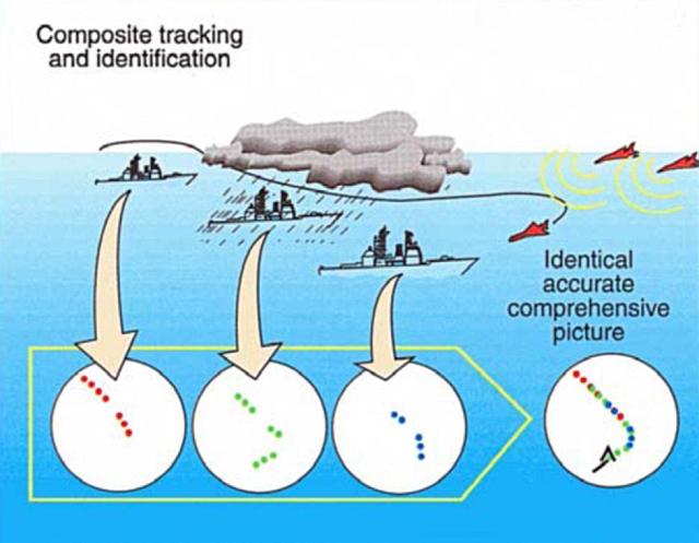 The next technological step for the
Russian industry is to extend their existing radar data fusion
capabilities into a full CEC capability following the US Navy model.
This would permit fusion of raw track data from multiple radars to
overcome the partial stealth capability in US types other than the
upper tier F-22A and B-2A. Example trial
track data as per: “The Cooperative Engagement Capability,” Johns
Hopkins APL Technical Digest 16, No. 4 (1995): 377-96, p. 388 in range, bearing
and elevation.
In summary, the kind of IADS Western aircraft will confront in the post 2010 timeframe will involve mixes of a wide range of radars and missile systems, with considerable diversity in operating bands, power-aperture performance, and often using sophisticated jam resistant modulation techniques, good frequency agility, and smart digital signal and data processing, with data fusion capabilities. The notion of a future IADS resembling Cold War era Soviet export systems is completely unrealistic. |
||||||||||||||||||
|
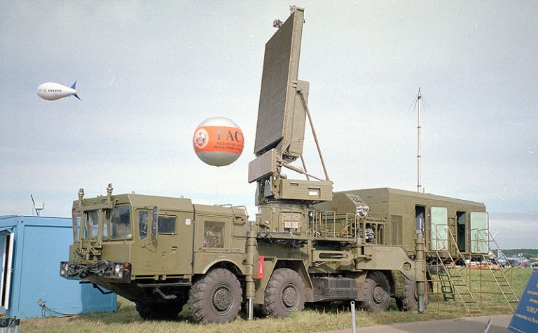
Contemporary IADS Elements
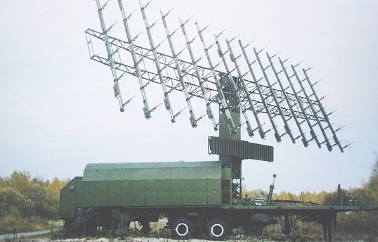 The
new 3 dimensional NNIIRT
1L119 Nebo SVU AESA
is an improved new
technology VHF
band SAM battery acquisition radars, and with
20 minutes to deploy. Stated tracking accuracy is 200 metres in range, 0.5° in azimuth,
and 1.5° in elevation, making it suitable as an
acquisition radar for the S-300PMU-1/2 and S-400 systems.
 S-400
Triumf
92N2
Grave Stone X-band high power-aperture engagement radar
deployed.
 S-400
Triumf
5P85TE2
TEL deployed.
 S-400 Triumf LEMZ 96L6E
Cheese Board L-band acquisition radar deployed. It replaces Cold War
era S-band radars such as the 76N6 Clam Shell and 36D6/ST-68U Tin
Shield series.
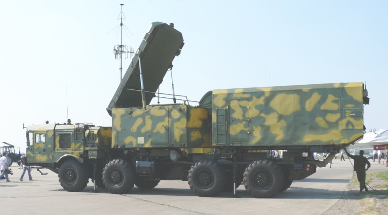
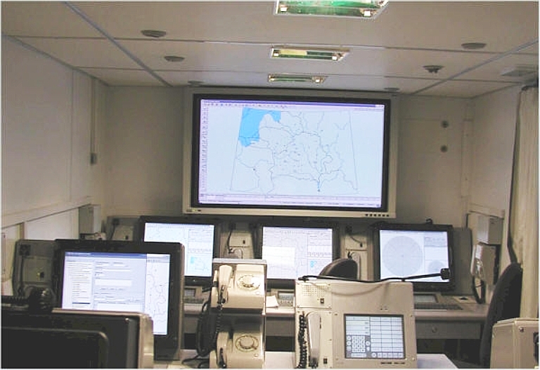
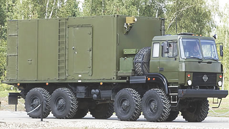 S-400 Triumf 55K6E
Command Post. The advent of COTS technology computing hardware and open
source software tools has seen explosive growth in the integration
capabilities available to Russian designers.
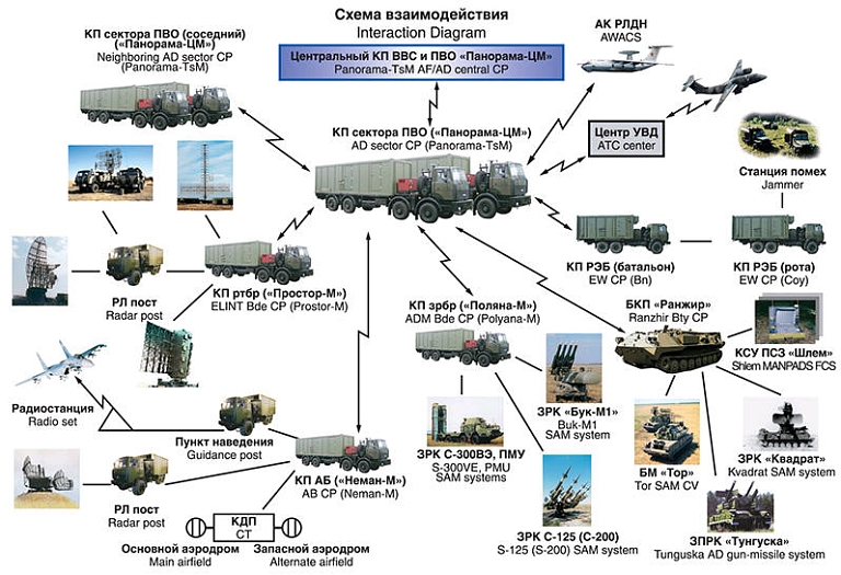 Diagram 1: The
Agat Panorama TsM Air Defence Area /
Sector Mobile Command Post (above, below) is a good
example of the highly integrated systems approach taken in the design
of contemporary IADS. It also illustrates the level of penetration
achieved by COTS computing technology in modern Russian designs. Note
that both legacy and contemporary missile batteries are supported, as
well as VHF band and microwave radars (Agat).
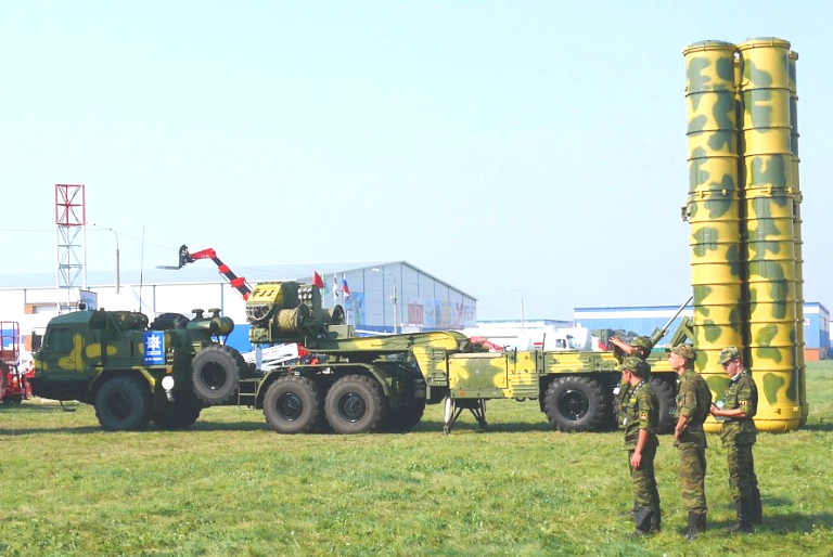
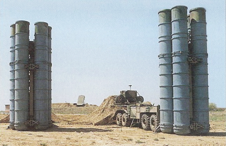 Deployed
S-300PMU2
Favorit
/ SA-20B Gargoyle battery. The 30N6E2 Flap Lid
engagement radar is visible in the distance . This battery is networked
via cables, and the telescoping network antennas are retracted (RuMOD).
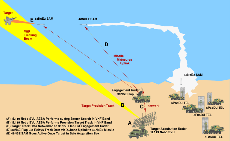 Diagram 2: Engaging a VLO/LO target (above) using the 1L119 Nebo SVU as a VHF band acquisition and tracking radar, and the 30N6E Flap Lid as a missile uplink channel (Author). 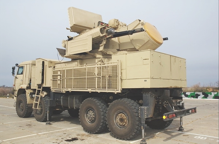 The latest
Pantsir S1 configuration at MAKS-2007, which incorporates a new
Phazotron designed agile beam
phased array engagement radar, derived from Phazotron's earlier effort
on the Zhuk MF PESA air intercept radar for the MiG-29 fighter. It is
intended to defend radars and missile batteries from attacks using
anti-radiation missiles or other weapons.
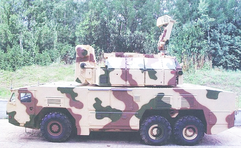 The Russian Tor M2E
or
SA-15D
Gauntlet is used to defend against low flying
aircraft as well as cruise missiles and guided weapons like smart
bombs. It is available on a tracked chassis, and more recently, a
purpose designed semi-hardened MZKT-6922 6 x 6
all terrain vehicle. The acquisition and engagement radars are both
PESA
technology (Kupol JSC).
|
||||||||||||||||||
Joint Strike Fighter Defence Penetration CapabilitiesThe Joint Strike Fighter, like
most contemporary combat aircraft designs, is intended to employ a
range of specific
design features to improve its survivability when penetrating hostile
air defences.
Joint Strike Fighter Stealth CapabilitiesThe Joint Strike Fighter is an
unusual airframe design, since it departs from many of the well
established ground rules in stealth shaping, established in other
designs such as the F-117A, B-2A, A-12A, YF-23A and F-22A Raptor.
Stealth
shaping is widely regarded to account for the first hundredfold
reduction in aircraft radar signature, compared to non-stealthy designs
of similar size, with application of lossy and absorbent materials used
to further reduce the signature where feasible.
|
||||||||||||||||||
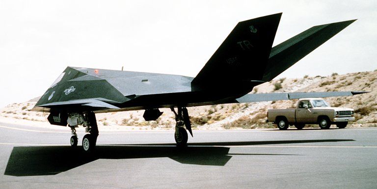 F-117A
Nighthawk.
Note
the slit exhaust apertures (above) and flat lower
fuselage (below).
 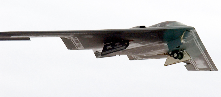 B-2A
Spirit.
Note the flat lower fuselage design.
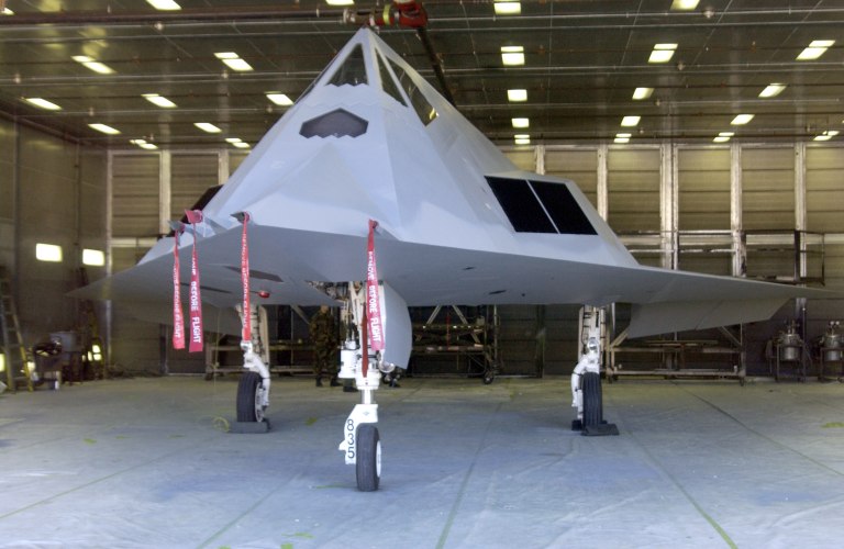
 The stillborn A-12A
Avenger
never flew. The lower fuselage and wing design is arguably the flattest
of any stealth design to date (US Navy images).
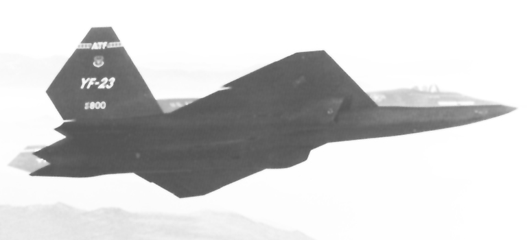
 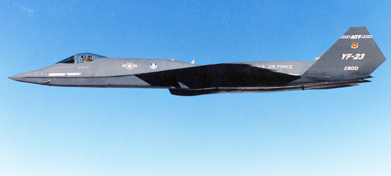 YF-23A prototype. The lower fuselage has
been designed with flat surfaces and low curvature blending for the
engine inlets, to minimise specular backscatter.
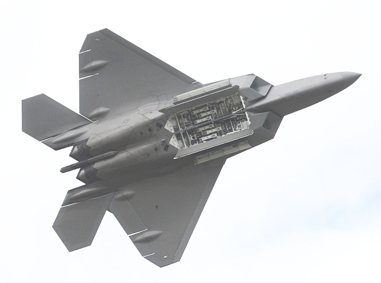
 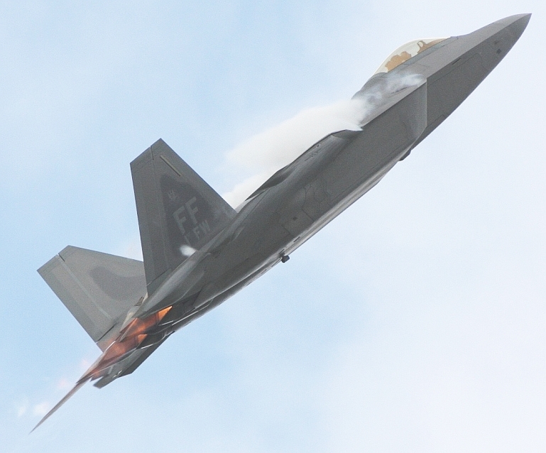 Production F-22A Raptor. The lower central
fuselage has been designed
with flat surfaces and aft fuselage with low curvature blending,clearly
intended to minimise specular backscatter (Images courtesy Miroslav
Gyűrösi).
 |
||||||||||||||||||
| The first
major departure from
established shaping conventions is the angular or aspect dependency
of the Joint Strike Fighter’s radar signature.
Study
of the shaping of the aircraft and comparison with other designs
shows that the Joint Strike Fighter can provide genuinely good
stealth performance only in a fairly narrow ~29° sector about the
aircraft’s nose, where the shaping of the nose, engine inlets,
panel edge serrations, and alignment of the leading and trailing
edges of the wings and stabilators results in the absence of major
lobes or “spikes” in the radar signature. The ±14.5°
angular limit is constrained by the principal reflecting lobe of the
leading and trailing edges of the wings and stabilators. The
signature degrades rapidly due to the influence of the lower centre
fuselage as the angle swings past ±45° off the nose, refer Diagram 4. An important development was that the SDD aircraft saw the original inlet design discarded and replaced with a scaled down inlet arrangement based on the F-22A design. Concurrently the lower fuselage was redesigned. In the SDD design, the beam/side aspect radar signature is especially problematic, due to the presence of multiple specular reflecting shapes, specifically due to singly and doubly curved lower fuselage surface feature shaping. The Joint Strike Fighter has a complex lower fuselage shape as well as a wing and fuselage lower join shape, unlike any other aircraft designed with stealth in mind, refer preceding images. The result of this design choice is that the beam/side aspect Radar Cross Section will be closer in magnitude to a conventional fighter flown clean than a “classical” stealth aircraft. This is an inevitable result of clustering no less than nine unique convex specular scattering shapes in the lower hemisphere of the aircraft. Diagram 3 illustrates this. Given that the dimensions of many of these shapes are of the order of metres, the application of absorbent or lossy coatings or laminates will not be sufficient to drive the critical lower hemisphere beam/side aspect signature down to values which qualify as VLO and thus “stealthy”. Refer Annex C. The aft sector radar signature
is
also problematic, as a result of the use of an axisymmetric nozzle
design. While the aft fuselage and tailboom shaping qualify as
“stealthy” across the upper bands, the nozzle presents as
a specular reflector in bands where the wavelength is comparable or
exceeds the dimensions of the nozzle segments. This is discussed
below. The
second major departure from established stealth conventions is that
the Joint Strike Fighter is designed to perform in the X-band, and
upper portions of the S-band, with little effort expended in
optimizing for the lower L-band, UHF-band and VHF-band. This design
strategy is consistent with defeating mobile battlefield short range
point defence SAM and AAA systems such as the SA-8 Gecko, SA-9
Gaskin, Chapparel, Crotale, Roland, SA-15 Gauntlet, SA-19 Grison and
SA-22 “Greyhound”, where limited radar antenna size
forces all acquisition and engagement functions into the X-band and
upper S-band. Joint Strike Fighter literature refers to this
optimization in terms of “breaking the kill chain”, the intent being to
deny the effective use of X-band engagement radars and X/Ku-Band
missile seekers, but not
acquisition radars in lower bands.
Such SAM systems are the category of “residual” threat which a battlefield interdiction aircraft will encounter once the F-22A force has “sanitized” an area by destroying the long range search/acquisition radars and area defence SAM batteries. With limited range and coverage footprint, but high mobility and autonomous capability, battlefield short range point defence SAM and AAA systems can “pop-up” from hidden locations and ambush interdiction aircraft at medium to low altitudes. Significantly, in a “sanitized” environment such air defence weapons are operating without external support from other sensors or the top cover provided by long range area defence SAMs such as the SA-12/23, SA-20 and SA-21. The engine nozzle presents a good case study of the band dependency of stealth performance in the Joint Strike Fighter design. In the upper X-band and Ku-band, the individual nozzle segments present as flat panels with a serrated trailing edge. The result will be a circular pattern of narrow reflecting lobes which will produce mostly good effect in these bands. However, in the lower bands this arrangement will rapidly degrade in behaviour to that of a truncated conical shape, which is a strong specular reflector. The resulting external shape related signature will be much the same as a conventional exhaust nozzle on a non-stealthy fighter, with an outer skin contribution and rim contribution. While the interior of the nozzle will be coated with broadband lossy materials and a tailpipe blocker used to obscure the turbine face, the signature of the nozzle exterior below the X-band cannot qualify as “stealthy”. Refer Annex C. |
||||||||||||||||||
 X-35 Dev/Val prototype (above) vs F-35 SDD
AA-1 (below). The clean wing fuselage join and flat low curvature lower
fuselage of the X-35 had the potential to yield quite good beam/side
aspect radar signature, but the revised SDD design discarded this
arrangement in favour of a much inferior contoured design, clearly
intended to accommodate the larger weapon bays. While the F-35 SDD
engine inlet arrangement is superior to the X-35 Dev/Val prototype inlet design, the
gains in the forward sector cannot overcome the performance losses
incurred in the beam/side aspect sectors (Images
via Air Force Link).
  Diagram 5: Very Low Observable airframe shaping
should be optimised to produce best effect, i.e. lowest radar cross
section, from those angles from which the aircraft is most likely to be
illuminated by a threat system such as an engagement or acquisition
radar in a Surface to Air Missile battery. This diagram shows the
cardinal depression angles for an aircraft at the tropopause,
accounting for the curvature of the earth and atmospheric refractive
effects which 'bend' the ray path between the aircraft and threat
radar. The specific angles in this diagram are determined using Russian
specifications for missile range, the SBF
refractive
model for short ranges, and an exponential
CRPL
refractive
model for ranges in excess of 100 nautical miles.
It is important to observe that in straight and level flight all
surface based threats are firmly in the lower hemisphere, putting a
premium on low Radar Cross Section in the angular range between 3.7 and
36.5 , as area defence missile systems will illuminate the aircraft
within this angular range. Point defence missiles systems and 'trash
fire' such as AAA and MANPADS are generally altitude limited to 10 - 15
kft and are a much less critical threat. A smart IADS operator will not
radiate until a potential target is close enough to get a steep
elevation angle for a shot, a tactic commonly associated with 'shoot
and scoot' operations - the cardinal example being Serbian ZRK Kvadrat
/ SA-6 operations in 1999 (Author).
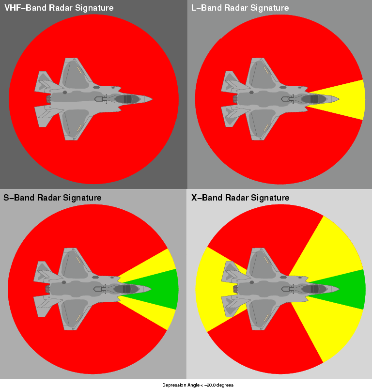
 The shaping changes to the inlet area and lower fuselage are prominent on these images of F-35A SDD prototype AA-1 (Images via Air Force Link).  Diagram 4 summarises the qualitative comparisons of Joint Strike Fighter shaping aspect and band dependency, with green denoting performance which qualifies as Very Low Observable, yellow as Low Observable, and red as order of magnitude closest to conventional reduced signature aircraft designs. The aircraft performs best in the X-band, and Ku-band, with performance declining through the S-band with increasing wavelength. In the L-band the axisymmetric nozzle design no longer produces useful effect, and the length of the inlet edges sits in resonant mode scattering rather than clean optical scattering, degrading performance. In the VHF band (~2 metres) Joint Strike Fighter airframe shaping has become largely ineffective. The aircraft will have a credible ability to defeat S-band search/acquisition radars, X-band engagement radars and X/Ku/K/Ka-band missile seekers only in the narrow ±14.5° angular sector under the nose. As the angle relative to the threat radars increases, the unfortunate lower fuselage shaping features will produce an increasingly strong effect with a cluster of “flare spot” peaks around 90° where the longitudinal panel and door edge joins produce effect. In the narrow ±14.5° angular sector under the tail, the design will produce best effect against X/Ku/K/Ka-band missile seekers, but less useful effect against X-band engagement radars due to their higher power-aperture performance. At S-band the nozzle exterior signature will become increasingly prominent, leading to loss of effect in the vicinity of the L-band. It is clear that these design choices were intentional and no accident. By confining proper stealth shaping technique only to the forward fuselage and inlet geometry, the designers avoided incurring the development, and to a lesser extent, the associated manufacturing costs of a fully stealthy design, with the YF-23A and F-22A presenting good comparisons. This is an acceptable optimization if the intent is only to defeat an isolated individual low power aperture pop-up short/medium range mobile battlefield air defence system in the category of the SA-6 Gainful, SA-8 Gecko, SA-9 Gaskin, Chapparel, Crotale, Roland, SA-11 Gadfly, SA-15 Gauntlet, SA-19 Grison or SA-22 “Greyhound”. It is a completely unsuitable optimization for a wide range of other threat types which are in service, and the associated characteristic engagement geometries. It is also a problematic optimisation where short/medium range battlefield air defence systems are deployed in a coordinated manner. The most generous description of the stealth design used in the Joint Strike Fighter is that it is 25% VLO, in the nose sector, 25% LO in the tail sector, and 50% “reduced observable” in the beam sectors, with a strong threat operating frequency and angular aspect dependency in stealth performance. It is clearly not a stealth design in the same sense as the F-117A Nighthawk, B-2A Spirit, YF-23A and F-22A Raptor, and to label it a “VLO design” is at best a “quarter-truth”, quite indifferent to the physical realities of the design and the threat systems it will need to defeat in future conflicts. Radio Frequency Surveillance System and CountermeasuresThe Joint Strike Fighter is to be equipped with a BAe Systems designed RFS, modeled on the larger ALR-94 system in the F-22A, but built to a lower manufacturing cost. Public disclosures include the use of six airframe apertures, comprising a pair in each wing leading edge and a pair in the trailing edges of the stabilators (some LM literature shows 10 rather than 6). In addition, the APG-81 radar’s AESA aperture will likely be used as an X/S-band interferometer for precision direction finding in the forward hemisphere, as is the case with the APG-79 AESAii.The manufacturer has made numerous claims about the intended use of the AESA as a high power directional jammer. Whilst this is feasible, the band coverage will be severely limited by the AESA design constraining its use primarily to upper S-band and X-band threat emitters, in a ±60° sector about the nose. There is also a risk that AESA jamming could be elicited by an opponent specifically to facilitate precision direction finding against the aircraft using an Emitter Locating System or interferometer antennas embedded in an engagement radar. Either scenario allows a missile battery to launch and guide an anti-radiation seeker equipped missile, or conventional missile. For instance, this specific operating regime is designed into the Antey S-300V or SA-12 system for exactly this purpose. As a penetration aid the RFS can be expected to provide similar surveillance and threat warning capabilities to other extant designs in this class. An open question is how good its detection capabilities will be for radars operating below 1 GHz frequency, given the constraint of six RFS receiver apertures. For comparison, the ALR-94 RFS in the F-22A is credited with no less than thirty antennas, compared to the six in the Joint Strike Fighter RFS. Cited defensive countermeasures for the Joint Strike Fighter include flares and chaff, but not internal active Electronic CounterMeasures (ECM) i.e. trackbreaking jammer equipment. APG-81 Multimode AESA RadarThe Northrop-Grumman APG-81 X-band pulse Doppler multimode radar developed for the Joint Strike Fighter is closest in concept to the APG-77(V)2 in the F-22A, and the APG-79 in the F/A-18E/F Block II aircraft. It is designed with a smaller number of modules than the APG-77(V)2, and with a lower per module power rating than the APG-79, making it shorter ranging than both alternatives, but comparable in frequency agility. Available briefing materials for the Joint Strike Fighter project display a very strong bias toward ground attack in APG-81 operating modes, with good capabilities for high resolution imaging and Ground Moving Target Indication.The radar has the potential to provide an automatic terrain following capability, but this is not stated in any Joint Strike Fighter literature. The Joint Strike Fighter would suffer a considerable range penalty if penetrating at low altitudes, and bird strike resistance of the canopy would present problems. Distributed Aperture SystemThe Joint Strike Fighter’s Distributed Aperture System (DAS) is an arrangement of six fixed medium resolution mid-infrared band thermal imaging devices, intended to provide full spherical coverage of the airspace around the aircraft. The pilot’s Helmet Mounted Display is intended to provide the pilot, in concert with the DAS, unobstructed spherical viewing ability.The DAS is an evolution of ideas trialed during the late 1980s, when the US Air Force evaluated options for Close Air Support, including a helmet steered thermal imaging device (FLIR) in the nose of an F-16B. It was found that this capability was especially valuable for Close Air Support, when a fighter needed to circle the target area and visually acquire the target of interest. A second function for the DAS which has emerged during the SDD effort is its use as an infrared Missile Approach Warning System (MAWS). As a MAWS the DAS is potentially very useful in the low and medium altitude Battlefield Interdiction and Close Air Support roles, as the short range point defence SAMs likely to be encountered frequently will be under power for much of their trajectories and thus produce a high infrared contrast exhaust plume which will be easily detected by the DAS. The utility of the DAS in dealing with longer ranging area defence SAMs is less clear, as such missiles will be much cooler and more difficult to detect, as the latter phase of their trajectories is typically well past rocket motor burnout. As relatively cool and fast moving targets, in many instances, a system like the DAS will not detect such a missile until it is very close and thus would more than often not yield sufficient warning time for defensive manoeuvre or effective countermeasures use. The DAS does have potential, where visibility is not obscured by low cloud or other atmospheric propagation impairments, to function as a launch warning system by detecting the infrared plume of an area defence missile during its launch and initial boost phase. This function is however dependent on having very favourable weather conditions. Networking and Data Fusion CapabilityA capability claimed frequently for the Joint Strike Fighter, but yet to be fully demonstrated even in a brassboard environment, is the use of networking and data fusion capabilities to collect threat information from other platforms, or other Joint Strike Fighter aircraft, and employ this for threat radar evasion or attack.At this stage the high capacity Joint Tactical Radio System remains in development and it is unclear when a mature capability will be available. This leaves the Joint Strike Fighter with its intra-flight datalinks and the MIDS/Link-16 datalink to provide networking connectivity. All of these choices present tactical risks in the IADS environment if they are operating in any mode which involves active radio-frequency emission by the Joint Strike Fighter aircraft. This is due to the proliferation of some very capable Emitter Locating Systems, which have historically demonstrated excellent capabilities in providing real time tracking of MIDS/Link-16 transmit capable targets. Technological growth in such systems will present genuine challenges for the LPI waveforms used in planned network designs. |
||||||||||||||||||
Assessing Joint Strike Fighter SurvivabilityWhile
the
Joint
Strike Fighter has
some stealth capability, a modern AESA and RFS, and the unique DAS,
it presents as a design which is not well balanced in overall
survivability terms.
The root of the survivability problems apparent in the Joint Strike Fighter is that its stealth capabilities are strongly dependent on aspect and threat radar operating band. If the threat is a single, isolated mobile battlefield short range point defence SAM system, the low power-aperture performance of such a weapon will provide poor detection capability against the Joint Strike Fighter in the nose and tail sectors, but much better capability in the beam aspect sectors, especially at steeper elevation angles. In such a scenario the SAM system will wait in ambush, not emitting, and then light up to snapshoot at the Joint Strike Fighter. The pilot’s best play is then to point the nose at the SAM system to cause the search and engagement radars, likely operating in the S-band and X-band respectively, to lose lock on the Joint Strike Fighter, while denying reacquisition by the SAM system’s adjunct thermal imaging tracker by shielding the exhaust nozzle. As such SAMs are most often command link guided, the loss of the engagement radar track will likely cause the missiles to lose guidance. The scenario where this play will fail is where the SAM system has an adjunct thermal imaging tracker with sufficient sensitivity, weather conditions permitting, to maintain a solid track on the aircraft. If the SAMs are infrared terminal homing designs, then this strategy may be less effective if the missile seekers have acquired the Joint Strike Fighter airframe. The current defensive package includes flares which will be effective against legacy seekers, especially single colour designs. If the SAMs are equipped with imaging focal plane array seekers, now becoming very common in air to air missile seekers, flares may be completely ineffective. Literature on the Joint Strike Fighter defensive suite makes no mention of provisions for a directed infrared countermeasure system, and packaging such would present difficulties in the densely packed Joint Strike Fighter design. If the threat is a single, isolated long range area defence SAM system, the high power-aperture performance of such a weapon will provide poor detection capability against the Joint Strike Fighter in the nose sector, but much better detection capability in the tail and the beam aspect sectors. Again, in such a scenario the SAM system will wait in ambush, not emitting, and then light up to shoot at the Joint Strike Fighter. Again, the pilot’s best play is then to point the nose at the SAM system to cause the engagement radar, likely operating in the X-band, to lose lock on the Joint Strike Fighter. Whether the SAM system can then maintain a track on the Joint Strike Fighter will depend primarily on the operating bands of its search radars, the geographical deployment of these relative to the engagement radar, and whether these radars have sufficient angular accuracy to guide the SAM round close enough to the Joint Strike Fighter for its seeker to lock on and reliably home in. The best case scenario for the Joint Strike Fighter is where the SAM system search radars are operating in the S-band or even X-band, and are collocated with the engagement radar. As a result of these conditions, pointing the nose at the engagement radar will likely cause all radars in the SAM system to lose track of the aircraft and the missile shot is defeated, providing the pilot reacts well before the missile seekers can gain lock. This technique will be much less effective in conditions where the angular relationship between the Joint Strike Fighter, the engagement radar, and the search radars, allows the SAM system to gain visibility of the Joint Strike Fighter from angles well off the nose with a high power aperture search radar accurate enough to produce midcourse guidance updates for a SAM round in flight. Under these conditions the Joint Strike Fighter is “pincered” as its stealth (VLO) capability is confined to a relatively narrow sector and it cannot “make itself invisible” to both threat radars at the same time. Under these conditions a conventional fighter would fall back on its omnidirectional ECM suite and attempt to jam the search and engagement radars, missile uplinks, and missile seekers, or use a towed decoy to seduce the missile seeker. If,
and only if, the threat radars operate within the band coverage of
the Joint Strike Fighter’s APG-81 AESA does jamming become a
viable option. If we consider a scenario where both threat radars are
not collocated, but both operate within the coverage of the X-band
APG-81, then the Joint Strike Fighter can point its nose at the radar
with the highest power aperture rating, and employ the AESA to jam
the remaining radars, assuming that they sit inside the ±60°
angular coverage of the AESA, and within its band coverage.
Thus assumes the AESA emissions will not be used to target a missile
shot against the Joint Strike Fighter.
If these specific conditions are not met, such as by a SAM system with search radars operating outside the band coverage of the AESA, or geographically located such that the AESA cannot be pointed at them, then the Joint Strike Fighter may not survive such engagements frequently. The root of these survivability problems in the Joint Strike Fighter design is that it provides robust stealth and robust jamming capabilities only in the sector under the aircraft’s nose. Its stealth capability from other angles, and in most bands, is poor or very poor, and without a proper internal jamming suite capable of covering all four quadrants around the aircraft, it is severely restricted in its choices of defensive tactics. This amounts to a basic failure in technological strategy in the Joint Strike Fighter design. When it was conceived, the X-35 airframe shaping provided potential for respectable stealth capability from most aspects, other than the problematic aft sector which was compromised in mid and lower bands due to the use of the cumbersome axisymmetric engine nozzle. Under these conditions, the design did not require internal ECM, towed decoys, or other active defensive measures, as most threat radars would have only achieved a reliable lock in the aft sector and outside the X-band. A good discussion of the reasoning initially behind the stealth design of the Joint Strike Fighter is contained in RAND Monograph MR719. It relates required stealth performance to the standoff range of weapons employed, for a range of threat scenarios based on 1997 assessments of Saddam’s Iraq, Iran and North Korea. The study concludes that the “Medium Stealth Fighter” (which became the Joint Strike Fighter) is viable with a 15 NMI or better standoff range glide bomb on Day 1 of an air war, for the postulated opponents and their air defence systems. The tabulated results in Fig 4.10 on page 46 of the RAND monograph are reproduced here for completeness:
RAND MR719 Analysis Results 1997, High Stealth Fighter (now F-22A), Medium Stealth Fighter (now F-35 JSF), and Low Stealth Fighter (e.g. F/A-18E/F). Since
the mid 1990s the strategic environment has changed profoundly. Only
two of the potential threat regimes then identified still exist. Both
have advanced in IADS capabilities, with both deploying the
S-200/SA-5 long range SAM, North Korea deploying the early S-300PMU /
SA-10 and Iran the more recent S-300PMU1 / SA-20 long range SAMs. China
has deployed many batteries of the S-300PMU / SA-10, S-300PMU1/PMU2
/
SA-20,
and HQ-9 long range SAMs. This
is a very different operating environment,
given
that
the medium range Hawk, S-75 / SA-2 Guideline, S-125 Goa
/ SA-3 and 3M9 / SA-6 Gainful were prevalent a decade ago, and
the S-300PMU / SA-10 deployed only by former
Soviet republics and satellites.
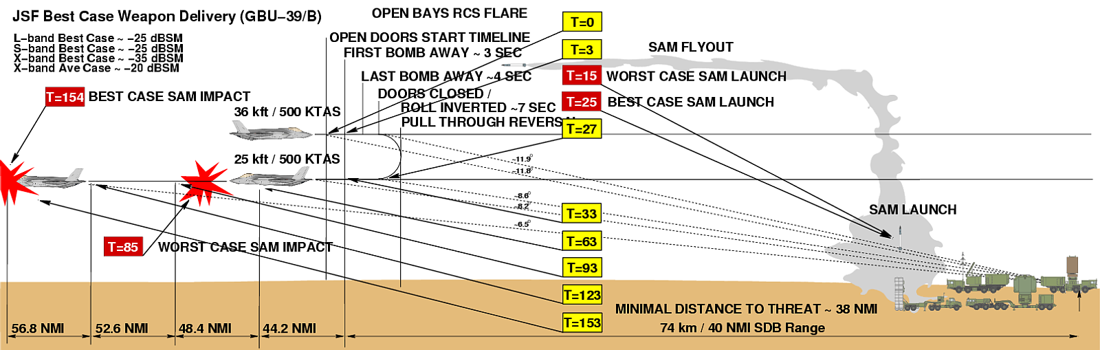
The pragmatic reality is that the threat environments which were used to define the stealth capability of what is now the Joint Strike Fighter are artifacts of history, since then re-equipped predominantly with longer ranging SAMs and more powerful radars. There has also been over a decade of technological evolution in Russian radar and missiles since 1997. In the simplest of terms, all of the basic technological assumptions used to define the stealth capabilities of the Joint Strike Fighter are no longer true. While potential threat nations replaced medium range SAMs with long range SAMs, and radars and SAMs evolved from analogue to digital, the Joint Strike Fighter’s design evolved in the opposite direction, with its stealth shaping progressively degraded in key areas. Diagram 6 illustrates a best case (for the Joint Strike Fighter) engagement using contemporary (and some legacy) long range SAM technology. As the Joint Strike Fighter evolved through the SDD program, the shaping of the lower fuselage departed strongly from the X-35 Dem/Val configuration, increasing the radar signature from the beam/side aspect. As a result the aircraft’s susceptible angular extent increased dramatically, leaving only the nose sector with a credible stealth capability. The inevitable conclusion at this point in time is that for the Joint Strike Fighter to become survivable against anything other than trivial isolated short/medium range SAM systems, it will require fundamental changes to its avionic and antenna aperture architecture, to incorporate a Digital RF Memory based active jammer with the angular coverage and emitted power levels to overcome the signature problems introduced by the SDD program.
The
problem with pursuing this necessary design change is that it will be
expensive in development costs, weight, power and cooling, even if
off the shelf jammer technology is employed. This is due to the need
to provide wideband antenna apertures for the jammer which do not
compromise or degrade what little remaining stealth capability is
left in the SDD Joint Strike Fighter design. While the wideband AESA
technology being developed for the Navy’s Next Generation
Jammer effort might be exploited, unlike the large F-22A which has
airframe provisions for sidelooking AESA arrays, the Joint Strike
Fighter design would require structural changes to make space
available.
The options of carrying external jammer pods on pylons, or jammers embedded in pylons, are technically simple but would further exacerbate the extant problems with stealth performance. Why the Joint Strike Fighter Program Office and manufacturer opted to disregard the well proven stealth shaping techniques used in the F-117A, B-2A, A-12A, YF-23A and F-22A remains an open question. The most plausible explanation is that the combined pressures of the “Cost As an Independent Variable” philosophy, and internal volumetric demands, forced the designers to expand lower fuselage cavities, the main undercarriage bays and weapon bays, and the only way this could be accomplished without major structural changes was by altering the lower fuselage shape, at the expense of beam/side aspect stealth performance. What is clear is that the introduction of the poorly shaped SDD lower fuselage design was not accompanied by the necessary analytical reassessment of the aircraft’s resulting survivability degradation and what measures would be required to overcome the reduction in stealth performance so produced. The failure in technological strategy was thus reinforced by a failure in program engineering management. |
||||||||||||||||||
Defence Penetration using the Joint Strike FighterAt this time there are two well established strategies in use for penetrating Integrated Air Defence Systems. The newer strategy could be best labelled as “evading detection through all aspect stealth” which was pioneered by the F-117A in Desert Storm and is currently used by the B-2A and F-22A. The F-22A adds supersonic cruise and very high penetration altitudes, which reduces exposure times and denies most SAM systems kinematic access to even engage the aircraft. This strategy is contingent upon the aircraft having genuine VLO capability in all four quadrants. The aircraft fly through the gaps between radars in the IADS, maintaining sufficient distance to remain undetected. This strategy is an evolution of the mid Cold War idea of terrain following penetration, where aircraft stayed at 200 ft AGL and evaded detection by remaining below the radar horizon of defending radars. The Soviet counter to this strategy was in the introduction of AWACS/AEW&C, mast mounted radars, digital clutter rejection processing techniques, and by increasing the density of radar coverage, thus ensuring that no airspace even at low altitude was unseen. These developments provided the imperative for the 1970s Have Blue program which resulted in the modern stealth paradigm. Modern IADS deployed as SAM belts are highly susceptible to penetration by all aspect stealth aircraft, as the cost of producing the required density of radars becomes infeasible. The Russian and Chinese technological strategy for dealing with penetrating all aspect stealth aircraft has been to develop a new generation of VHF band radars, including multistatic forward scattering radars. These will reduce opportunities for undetected penetration, especially by fighter sized aircraft, as the VHF radars defeat shaping measures and materials designed for S-band and X-band threats. The US Air Force technological strategy for dealing with this counter-strategy is the use of the F-22A Raptor, armed with the GBU-39/B Small Diameter Bomb, for lethal suppression of such radars. A pair of F-22As, armed with sixteen SDBs in total, can overwhelm the point defence SAM systems defending critical search radars. The inferior “single aspect stealth” capability of the Joint Strike Fighter denies it the option of penetrating a modern IADS SAM belt. The depth of the IADS simply makes it geometrically impossible to find a path between search radars where the combination of distance and relative aspect would allow it to penetrate unseen. This is exacerbated by the increasing availability of modern digital VHF, UHF and L-band search radars, especially radars with 3D capability and the accuracy to guide long range area defence SAMs. The limited 40 NMI standoff range and time of flight of the GBU-39/B SDB glidebomb denies the Joint Strike Fighter the use of the lethal suppression strategy flown by the F-22A. Most missile batteries will have “scooted” away from the bombs’ aimpoints before they arrive. Indeed, the range from which the Joint Strike Fighter would need to release the SDB would in many IADS geometries leave it exposed to long range SAM shots, which it is ill equipped to handle. The result of increasing IADS capabilities and the degradation of the Joint Strike Fighter’s stealth design through the SDD leaves it with only one tactical option for penetrating an IADS environment. That option could be best labelled as “shooting a path through defences”, which is essentially the “conventional” model pioneered and perfected during the Vietnam conflict and incrementally improved since then. In this model a strike package intended to penetrate an IADS will be escorted by aircraft armed with anti-radiation missiles such as the HARM family of weapons. These are launched in large numbers to destroy threat radars which continue to emit, and force others to shut down for fear of attack. This strategy in its basic form is now in its twilight years, and basically only useful against legacy IADS equipped with Cold War era weapons. This is a result of two basic changes in IADS operating doctrine and supporting technology. The first of these is the adoption of active emitting decoys which will seduce some fraction, if not ideally all of the anti-radiation missiles launched. The second of these is the modern practice of defending search and engagement radars with “counter-PGM” capable short range point defence missiles, such as the SA-15, SA-19, SA-22 and the 9M96E missiles in the SA-21 system. Such missiles are intended to shoot down inbound anti-radiation missiles – or glidebombs. As a result, this strategy will require heavy saturation attacks as a large proportion of the anti-radiation missiles launched will be decoyed or soaked up by point defence SAM defensive fire. A strike package intending to penetrate an area defended by a single battery of SA-20/21, supported by the SA-15, SA-19, SA-22 and/or the 9M96E missiles in the SA-21 system, would need to deliver of the order of 32 or more anti-radiation missiles to exhaust the typical point defence SAM ready round loadouts. In 2002 the Threshold Weapons package for the SDD Joint Strike Fighter included up to four externally carried AGM-88 HARM anti-radiation missiles, this presumably including planned derivatives such as the multimode seeker equipped AGM-88E AARGM. A year later the HARM vanished from the SDD weapons package. This has important implications, assuming that the HARM or a follow-on weapon can be successfully cleared from the long and forward displaced pylons used by the Joint Strike Fighter. The first of these is that the capability to use this IADS penetration technique will not be available until the 2020 timeframe, post SDD. More importantly, the degradation in the stealth capability of the Joint Strike Fighter through the SDD program is forcing the Joint Strike Fighter into the use of a defence penetration strategy no different to that used by legacy aircraft, which is inherently expensive in expended munitions and in the number of sorties required to achieve a given effect. There is no economic advantage to be found in this game by using a Joint Strike Fighter instead of a HARM shooting legacy type such as the F-16, or F/A-18 (with its aeroelastic limitations) or, better still, the very capable HARM shooting F-111. One of the principal reasons which justifies the additional design and maintenance expenditures on stealth aircraft is that significant economies can be produced by using all aspect stealthy penetration techniques – only the aircraft carrying bombs to strike targets need to be deployed, and a minimum of supporting aircraft are then necessary, with munitions expenditures limited to the bombs required to do the job. The SDD Joint Strike Fighter with its impaired stealth cannot use this strategy, and the operational economics are thus degraded to those of legacy aircraft, but still incurring nearly all of the cost burdens of a proper all aspect stealth design. In technological strategy terms the Joint Strike Fighter design is thus “pennywise and pound foolish” in the sense that the design is carrying most of the cost burden of an all aspect stealth aircraft, but it is not stealthy enough to exploit the benefits which are inherent in a good stealth design, and thus incurs most of the operational economic burdens of a non-stealthy legacy aircraft. |
||||||||||||||||||
ConclusionsThe Joint Strike Fighter is demonstrably not a true stealth aircraft in the sense of designs like the F-117A, B-2A and F-22A, as its stealth performance varies much more strongly with aspect and threat radar operating frequency band. The degradation of the initially intended Joint Strike Fighter stealth performance occurred during the SDD program when a series of design changes made to the lower fuselage of the aircraft resulted in fundamental shaping changes in comparison with the X-35 Dev/Val prototype aircraft. The Joint Strike Fighter SDD design departs strongly from key stealth shaping rules employed in the development of the F-117A, B-2A, and F-22A, or the never built YF-23A and A-12A designs. As a result the tactical options available to Joint Strike Fighter users when confronted with penetrating modern Integrated Air Defence Systems (IADS) are mostly those necessary to ensure the survival of non-stealthy legacy aircraft types. The result of these limitations is that the operational economics of a fighter force using the Joint Strike Fighter will be much inferior to a force using a true all aspect stealth aircraft such as the F-22A Raptor. As with claims made for Joint Strike Fighter air combat capability, claims made for the Joint Strike Fighter concerning the penetration of IADS equipped with modern radars and SAMs are not analytically robust, and cannot be taken seriously. Moreover, it is clear that future Joint Strike Fighter users will pay a significant price penalty for a stealth capability unable to deliver much, if any, return on such investment. |
||||||||||||||||||
References and
Bibliography
|
||||||||||||||||||
Endnotes i
Refer Donald Stevens, Bruce Davis, William Stanley, Daniel M. Norton,
R. M. Starr, Dan Raymer, John Gibson, Jeff Hagen, Gary Liberson, “The
Next-Generation Attack Fighter /Affordability and Mission Needs, RAND
Monograph MR719”, Project Air Force, 1997, Santa Monica, CA, USA.
ii
“Six low-observable EW apertures are distributed around the
aircraft--two embedded inside the leading edge of each wing and one in
the trailing edge of each horizontal tail. Located inside the
aerodynamic mold line of the aircraft, the EW apertures are designed to
allow the aircraft to perform missions without altering its radar
cross-section. One aperture can be used to identify the mode of a
hostile radar, and two or more apertures can be used to determine the
direction of enemy emissions. There are three, four-channel wideband EW
receivers.”; “The self-protection system includes a response manager
and RF/IR countermeasures. Two countermeasure dispensers are located in
the aft area of the aircraft, carrying IR flares and chaff.”; “The
F-35's high-gain, electronically steered radar array provides jamming
support under the control of the EW system.”; refer Ron Sherman, F-35
Electronic Warfare Suite: More Than Self-Protection, Avionics Magazine,
April, 2006, URL: http://www.aviationtoday.com/av/categories/military/845.html.
|
||||||||||||||||||
|
|
||||||||||||||||||
Imagery
Sources: Author; www.jsf.mil, US DoD.
|
||||||||||||||||||
|
Air Power Australia Analyses ISSN 1832-2433 |
||||||||||||||||||
|
|||||||||||||
|
|
|
|
|
|
|
|
||||||
|
|
|
|
|
|
|
|
||||||
 [Click for more ...]") |
|||||||||||||
| Artwork, graphic design, layout and text © 2004 - 2014 Carlo Kopp; Text © 2004 - 2014 Peter Goon; All rights reserved. Recommended browsers. Contact webmaster. Site navigation hints. Current hot topics. | |||||||||||||
|
Site Update
Status:
$Revision: 1.753 $
Site History: Notices
and
Updates / NLA Pandora Archive
|
|||||||||||||
|
|
Tweet | Follow @APA_Updates | |||||||||||
|
|
|||||||||||||
|
|
|||||||||||||


